64 | Manual ZX0 HB 600 en - Revision 05
The off-circuit condition on the cable side is tested by means of
the capacitive voltage indicator (pick-off on the outer cone). Three
systems can be used:
− LRM-system,
− KVDS-system, or
− CAVIN-system.
Observe the instruction manual for the system used.
− Check the function of the equipment immediately before
use. The optical display must be clearly visible!
− The sockets of the capacitive indicator system must never
be short-circuited, except during voltage testing on the
switchgear.
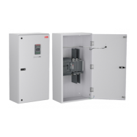
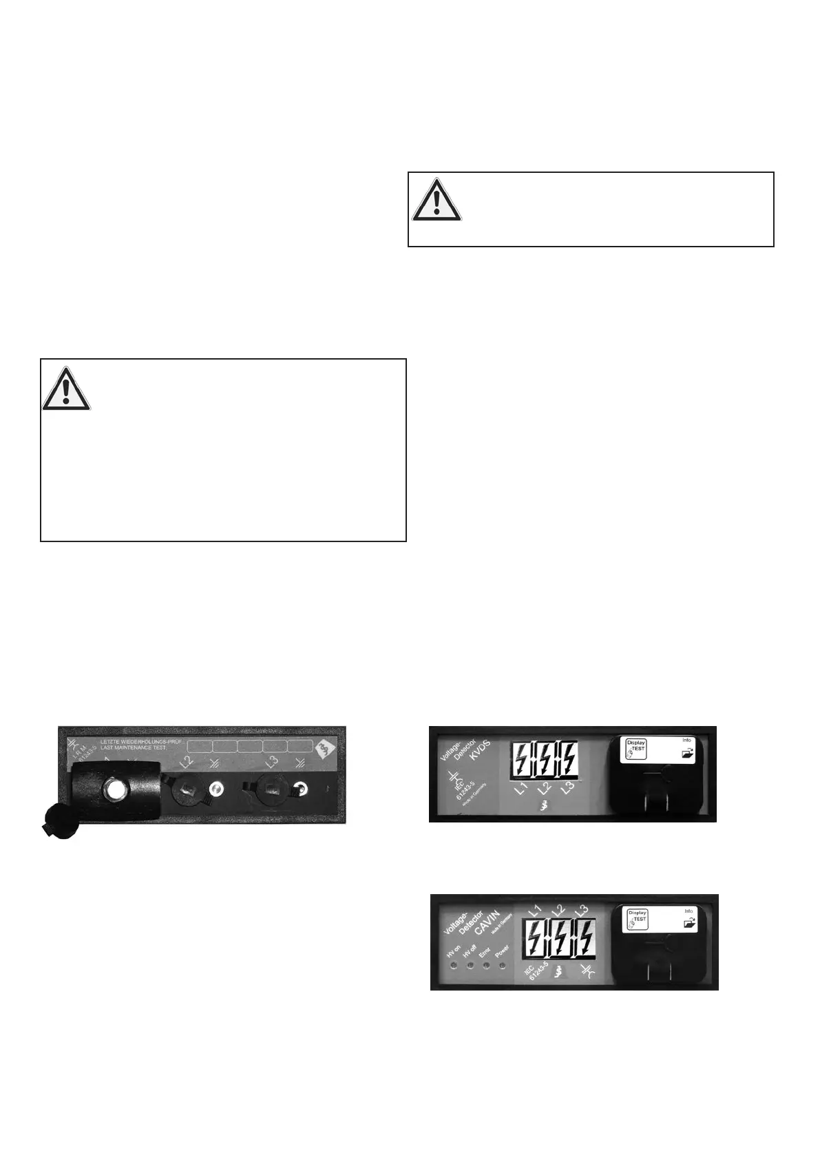
Testing for the off-circuit condition is performed with the display on
the unit. No separate display unit is required.
5 Test procedures
5.1 Testing for the
off-circuit condition
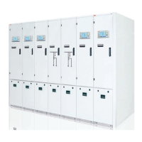
Fig. 5.1.1.1: LRM system with display unit
Testing for the off-circuit condition is performed with a plug-in dis-
play unit (design to IEC 61243-5) at the three pairs of measuring
sockets.
Perform repeat tests on the system in accordance
with IEC 61243-5, for instance with interface tester
KSP. Observe the instructions for the interface
tester.
5.1.1 LRM-system
5.1.2 KVDS- and CAVIN-systems
Fig. 5.1.2.2: CAVIN-system
Fig. 5.1.2.1: KVDS-system
 Loading...