New HC Series User Manual - 13 -
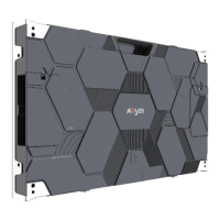
Step 4:
After all the cabinets assembled,
connect all the power and data
cables.
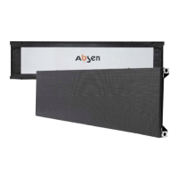
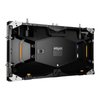
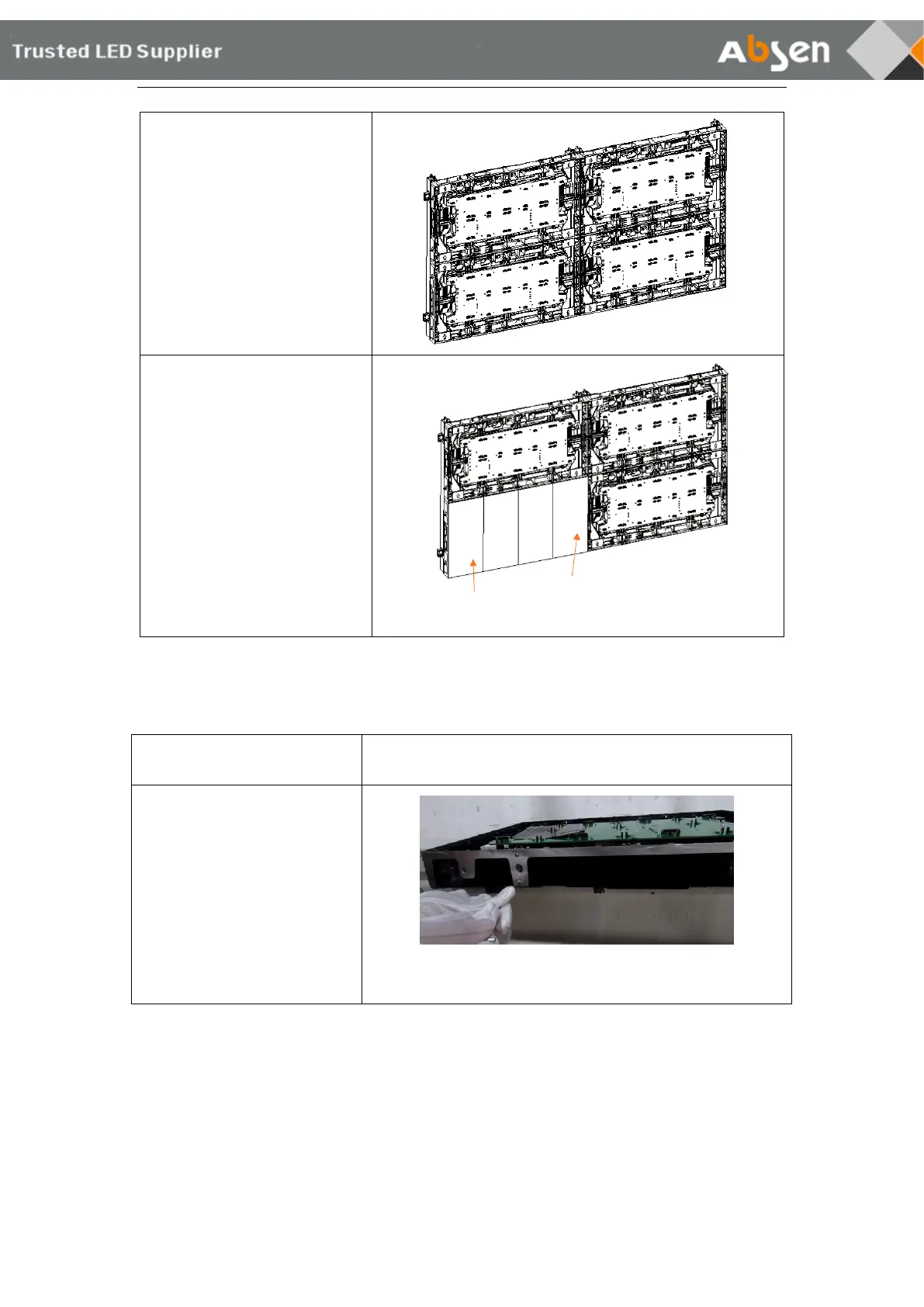
Step 5:
The installation module should
be installed according to the
corresponding number of the
module and the cabinet.
From the front view, module XX-
1 is installed on the leftmost side
of the cabinet, and module XX-4
is installed on the rightmost side
of the cabinet. (Note: "XX"
represents for cabinet number).
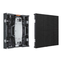
3.2 Connecting Plate Installation
Step 1:
Remove the cabinet from the
packaging and remove the
anti-knock screws that need to
be installed in the bottom row
of the whole screen. The anti-
knock screws are at the bottom
of the cabinet, 4 for each
cabinet.
 Loading...