10
ENGLISH
OPTION BOARDS
Three types of option boards can be used in the E-213: the Digital Input Board DAC-10, the Analog Disc Input Board AD-9, and the Line Input Board LINE-9. These
boards can be installed in the rear-panel slot as required.
USING AN OPTION BOARD
Playback of CDs or similar with digital input
Install the Digital Input Board DAC-10.
Caution: Be sure to turn power to the E-213 off before installing or
removing an option board.
✽ The board can handle digital output signals from a CD player, DAT recorder,
MD recorder or another digital component with a sampling frequency of up
to 96 kHz.
The connection can be made with coaxial or optical fiber cable.
Remove protective cover from
connector.
Plug
Analog Disc (AD) Input
Install the Analog Disc Input Board AD-9 (or AD-10).
Caution: Be sure to turn power to the E-213 off before installing or
removing an option board.
Before inserting the board, the following settings must be made using
the DIP switches on the board.
Note: Use a sharp pointed object to move the switch levers and make
sure that the levers are set fully to one side. If switch settings not
specified here are selected, correct performance will not be
achieved.
A S1, S2: MM/MC selection
B S3: Input impedance selection for MC: 10/30/100 ohms
C S4, S5: Subsonic filter ON/OFF
mm
mm
m The Analog Disc Input Board AD-10 and the Line Input Board LINE-10 can also be used.
Connector with shutter
Push inwards to open
shutter.
Insert plug firmly into connector
with lettering facing up.
Connector with
protective cover
Lettering
Pull protector off plug tip.
Insert plug firmly into connector
with lettering facing up.
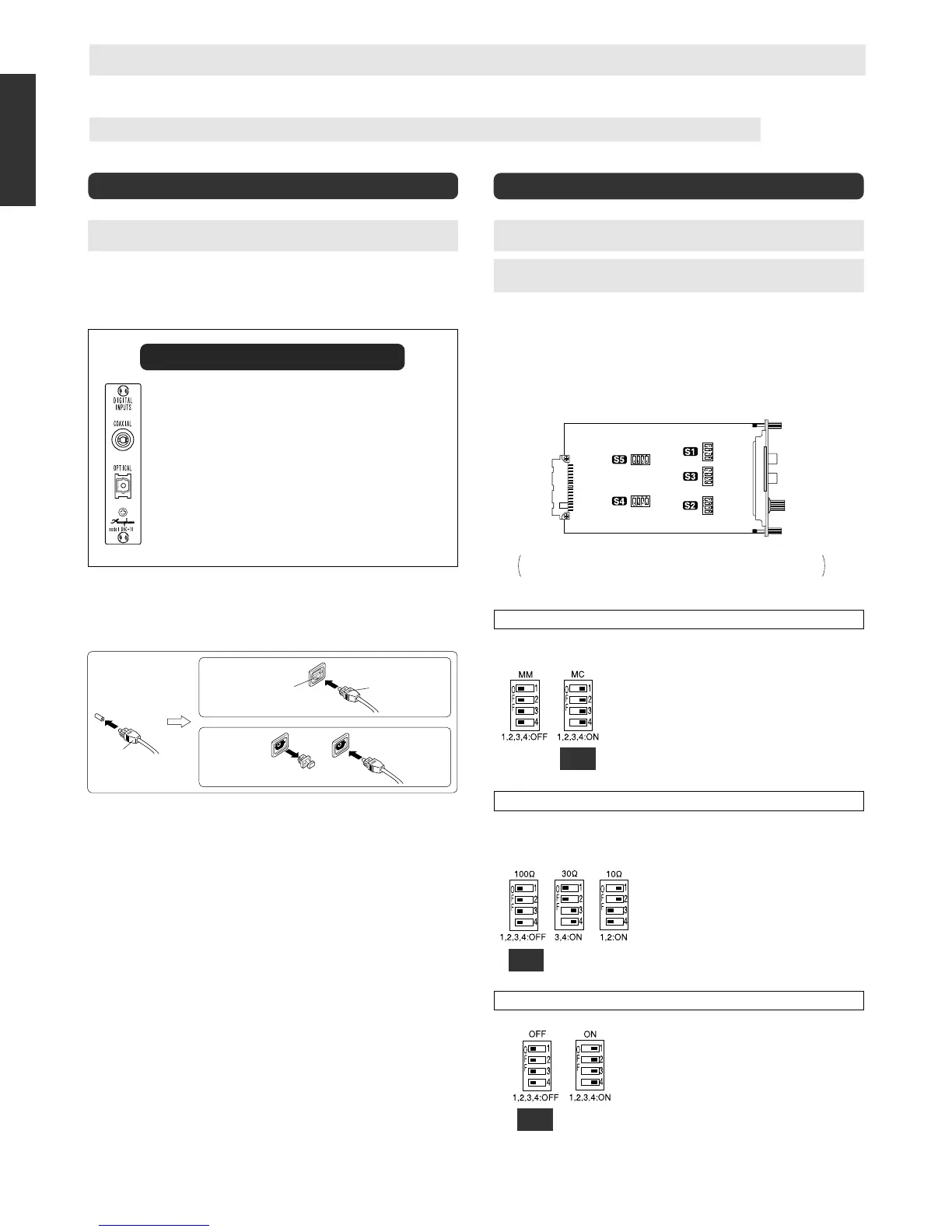
AD-9 component side
The illustration shows the position of the switches on the board.
The switch position is identical for the AD-9 and AD-10.
Digital Input Board DAC-10
This board can be used for optical and/or coaxial input of
digital music signals from source components with digital
output.
Connection cables
COAXIAL: For 75-ohm coaxial cable
OPTICAL: For Toslink optical fiber cable
(OPTICAL input has automatic priority.)
Guaranteed specifications, standards
Input format: EIAJ CP-1201/AES-3 compliant
Sampling frequency:
32 – 96 kHz
Digital input: COAXIAL 0.5 Vp-p, 75 ohms
OPTICAL –27 to –15 dBm
A
S1, S2: MM/MC equalizer gain selection
Factory
default
setting
MM: For moving magnet cartridges with high
output
Gain: 36 dB
Input impedance: 47 kilohms
MC: For moving coil cartridges with low output
Gain: 62 dB
Input impedance: As selected with S3
m Be sure to set both the S1 and S2 switches to the
same position.
Factory
default
setting
B
S3: MC input impedance selector
As a general guideline, set this switch according
to the rated internal impedance of the MC cartridge.
20 ohms or more: 100 Ω position
Less than 20 ohms: 30 Ω or 10 Ω position
m Generally, the input impedance setting should
be about 2 to 3 times the rated cartridge
impedance. However, since the requirements
of some cartridges may vary, the final setting
should be determined by ear.
m The S3 switch affects both the left and right
channels.
C
S4, S5: Subsonic filter on/off
Factory
default
setting
This filter has a cut-off frequency of 25 Hz and a
steep attenuation slope of –12 dB/octave. It cuts
off unwanted subsonic signal components without
affecting the audible range. Removing subsonic
noise components is useful for example to stop
excessive woofer excursions caused by record
warps, turntable rumble, etc.
m Be sure to set both the S4 and S5 switches to
the same position.
Note
When both the COAXIAL and the OPTICAL inputs are connected, the OPTICAL
connector is automatically given priority.
m When signals are present at both connectors, the source connected to the
OPTICAL (Toslink optical fiber) input will be heard.
m To play back the signal from the component connected to the COAXIAL
connector, disconnect the OPTICAL input or turn power to the component
connected to the OPTICAL input off.
m If a signal appears at the OPTICAL input during playback of the signal from
the COAXIAL input, playback will switch to the OPTICAL input.
Connection cables
COAXIAL: Use a 75-ohm coaxial cable with RCA plugs.
OPTICAL: This is a connector for EIAJ standard Toslink optical fiber cable.
Playback
a Verify that the VOLUME control is turned fully down and then turn on the
E-213 and the other components. Select the OPTION position of the input
selector. (This position is for the slot where the DAC-10 is installed.)
b Set the source component to the play condition and adjust the volume to a
suitable level.
 Loading...