2
Notes
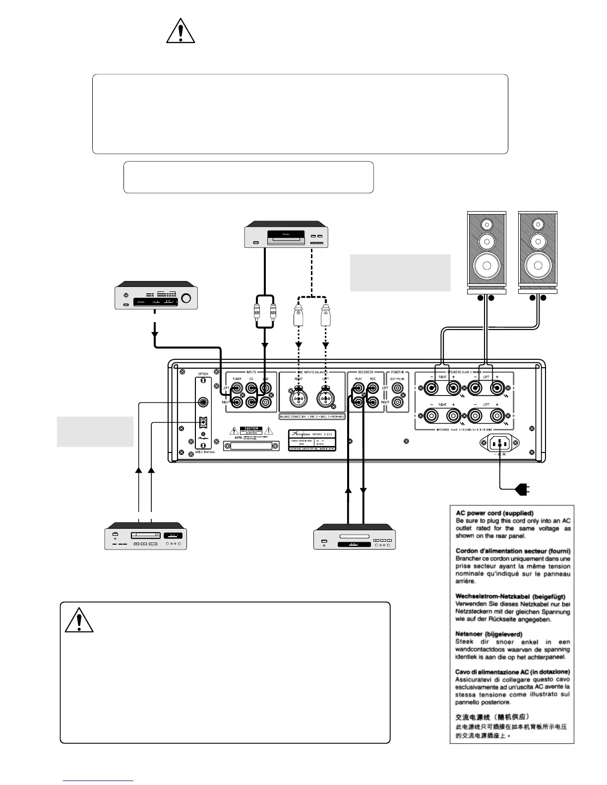
●
For connection between the DAC-10 and digital equipment, use a 75-ohm coaxial cable or
optical fiber cable.
●
For analog input/output connections, use shielded audio cables and take care not to mix up
left and right channels.
●
Do not make connections to a component with balanced and unbalanced cables at the
same time. Otherwise ground loops may occur, which can cause noise.
CAUTION:
Before making connections, be sure to switch
the power to all components off.
CONNECTIONS
●
This set relies on cooling with a natural flow of air between the ventilation
holes on the top and bottom. When installing the set, leave at least 10 cm of
space at both sides, the top and the back to allow for normal ventilation.
●
Do not place any object containing liquid (vases, flower pots, bottles with
cosmetics or chemicals, etc.) on top of the unit. If a spill occurs, there is a risk
of fire and electric shock.
●
If there is a problem with the unit or if malfunction occurs, always disconnect
the power cord from the AC outlet! This is absolutely essential, because simply
setting the power switch to OFF will not completely separate the unit from the
AC source.
WARNINGS
Option board installation example shown in illustration
●
OPTION: Digital Input Board [DAC-10]
modelDAC-10
DIGITAL
INPUTS
COAXIAL
OPTICAL
DIGITAL OUT
STEREO
MH
Z
CH
MEMORY
SELECTIVITY METER
NORMAL SIGNAL
mm
B
compacr disc player
DP-65V
ANALOG OUT
STEREO
MH
Z
CH
MEMORY
SELECTIVITY METER
NORMAL SIGNAL
0 1 2 3 4 5
fm stereo tuner
model T-109V
output level
1
2
3
4
5
6
7
8
9
10
0
station
LINEIN
LINEOUT
STEREO
MH
Z
CH
MEMORY
SELECTIVITY METER
NORMAL SIGNAL
Audiocableswith
RCA-typeplugs
Balanced
cables
CDplayer
Useshieldedcablesforaudio
connections(2-conductor
shieldedcablesforbalanced
connections).
*
ANALOG
OUTPUTS
Recorder
Opticalfiber
cable
75-ohmcoaxial
cable
CDplayer,DATrecorder,
MDrecorder,orother
digitalcomponent
See"OptionBoards"
formoreinformation
onthisconnection.
Tuner
Speakers
Left Right
+−
+−
 Loading...