Chapter 1 23
Hardware Specifications and Configurations
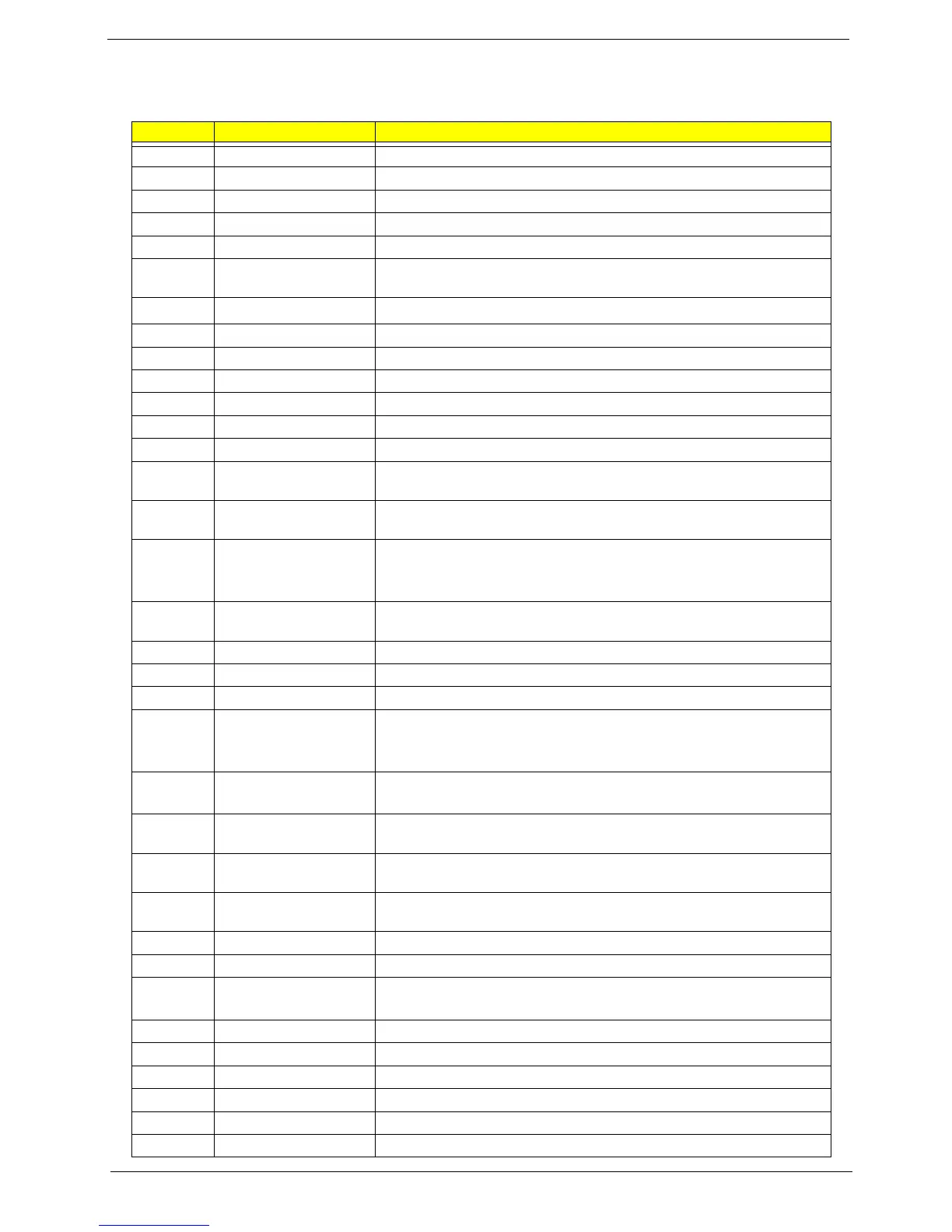
Pin Definition Between Main Board and I/O Board
Item Specification
1 Teletext_RGB_B ( 6 ) ‘Blue’ signal comes from Teletext decoder IC.
2 Teletext_RGB_B ( 6 ) ‘Green’ signal comes from Teletext decoder IC.
3 Teletext_RGB_B ( 6 ) ‘Red’ signal comes from Teletext decoder IC.
4 Teletext_fast_blanking Fast blanking signal for the use of Teletext decoder IC on I/O module.
5 Teletext_start Main board issues it for the use of Teletext decoder IC on the I/O module.
6 SCART_aspect_ratio_1 Aspect ratio indicator signal comes from pin-16 of ordinary SCART
connector.
7 DAC_RST (1)
Main board used this pin to reset I
2
C DAC on current I/O module.
8 TX_232 ‘TX’ signal of UART
9 SVHS_2_C (3) ‘Chrominance’ signal of SVHS-2
10 SVHS_1_Return (3) Return path paired with Y and C of SVHS-1.
11 SVHS_1_Y (3) ‘Y’ of SVHS signal set 1.
12 CVBS_1_ CVBS-1
13 GND_1_of_(3) Power ground
14 Audio_Center_GNd_gn
d (2)
‘Ground’ path paired with audio ‘Center’
15 Earphone_for_subpictu
re_L (2)
Audio ‘Left’ channel paired with sub-picture.
16 Audio_Center_Gnd_gn
d (2)
Audio woofer signal. After decoding Dolby digital or other surround audio,
digital receiver sends this woofer signal to LCDTV main board for further
processing.
17 Audio_Rear_L_R_Gnd
_of_R (3)
'Right' signal of audio rear channels.
18 YUV_1_Pr ( 6 ) 'Pr' of YUV signal set 1.
19 YUV_1_Pb ( 6 ) 'Pb' of YUV signal set 1.
20 YUV_1_Y ( 6 ) 'Y' of YUV signal set 1.
21 Audio_Front_L-
R_Gnd_of_R (3)
'Right' channel of surround audio.
After decoding Dolby digital or other surround audio, digital receiver sends
this signal to LCDTV main board for further processing.
22 Teletext_Vs ( 3, from
mainboard )
Vertical Sync. Signal issued by LCDTV main board for use of Teletext
decoder IC on the I/O module.
23 Teletext_RGB_B_Retur
n (6)
'Blue' signal return for Teletext decoder IC.
24 Teletext_RGB_G_Retur
n (6)
Return path paired with 'Green' signal comes from Teletext decoder IC.
25 Teletext_RGB_R_Retur
n (6)
Return path of 'Red' signal comes from Teletext decoder IC.
26 GND_2_of_(3) Power ground
27 SCART_mode_det_1 SCART mode detection ( RGB or CVBS )
28 RESET_I_O_Module LCDTV main board uses this pin to reset all components inside the I/O
module.
29 RX_232 'RX' signal of UART
30 SVHS_2_Return ( 3 ) Return path paired with Y and C of SVHS-2
31 SVHS_2_Y ( 3 ) 'Y' of SVHS signal set 2.
32 SVHS_1_C ( 3 ) 'Chrominance' signal of SVHS-1.
33 CVBS_1_Return ( 2 ) Return path for CVBS-1
34 CVBS_1_Signal (1) CVBS-2

 Loading...