EasyManuals Logo

Acer Aspire 1650 Series User Manual

Acer Aspire 1650 Series
103 pages
To Next Page IconTo Next Page
To Previous Page IconTo Previous Page
Page #51 background imageLoading...
Page #51 background image
46 Chapter 3
Disassembly Procedure Flowchart
The flowchart on the succeeding page gives you a graphic representation on the entire disassembly sequence
and instructs you on the components that need to be removed during servicing. For example, if you want to
remove the system board, you must first remove the keyboard, then disassemble the inside assembly frame in
that order.
Start
Battery
HDD Cover ODD Module
RAM/Wireless
Cover
E*2
K*2
HDD Module
Wireless LAN
Card
Memory
IO Bezel
*2
*2
Heatsink
Cover
*2
Thermal
Module
CPU
ODD
Connector
Board
ODD Holder
ODD Drive
*6
*3
Middle Cover
*2
Keyboard
*4
(right and left hinges)
LCD Module
*2
Switch Board
*5
*18
Lower and
Upper Case
Assembly
Upper Case
Assembly
Lower Case
Assembly
3-in-1 Cover Speaker Set Modem Board
Touchpad
Bluetooth
Module
Touchpad
Board
Touchpad
Bracket
*2
Main Board
*4
*2
*2 screw nuts
VGA Heatsink
*3
download service manual and resetter printer at http://printer1.blogspot.com

Table of Contents

Questions and Answers:

Question and Answer IconNeed help?

Do you have a question about the Acer Aspire 1650 Series and is the answer not in the manual?
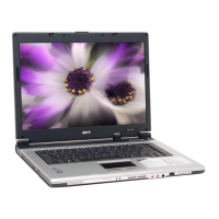
Acer Aspire 1650 Series Specifications

General IconGeneral
Operating SystemWindows XP Home or Professional
RAMUp to 2GB DDR
Storage40/60/80GB Hard Disk Drive
Optical DriveDVD/CD-RW combo or DVD±RW
Battery6-cell Li-ion
Memory TypeDDR
Display Resolution1024 x 768 (XGA)
Hard Drive InterfaceATA-100
Networking10/100 Mbps Fast Ethernet; 802.11b/g Wireless LAN
PortsRJ-45, RJ-11, Headphone, Microphone
Weight2.8 kg (6.17 lbs)

Related product manuals