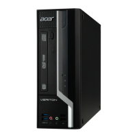
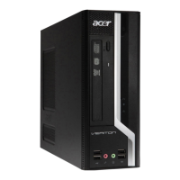
vii
System Tour 1
Features 1
Block Diagram 5
System Components 6
Front Panel 6
Rear Panel 7
Hardware Specifications and Configurations 8
Power Management Function(ACPI support function) 11
System Utilities 12
CMOS Setup Utility 12
Entering CMOS setup 13
Navigating Through the Setup Utility 13
Setup Utility Menus 14
System Disassembly 27
Disassembly Requirements 27
Pre-disassembly Procedure 28
Removing the Side Panel 29
Removing the Front Bezel 30
Removing the Heat Sink Fan Assembly 31
Removing the Processor 32
Removing the Optical Drive 33
Removing the Hard Disk Drive 34
Removing the Power Supply 37
Removing the VGA Card 39
Removing the Memory Modules 40
Removing the Front I/O and Card Reader Boards 41
Removing the Intrusion Alarm Cable 43
Removing the Power Switch,OBR and LED Cable Assembly 44
Removing the Mainboard 46
System Troubleshooting 48
Hardware Diagnostic Procedure 48
System Check Procedures 49
Power System Check 49
System External Inspection 49
System Internal Inspection 49
Beep Codes 50
Checkpoints 51
BIOS Recovery 54
Jumper and Connector Information 55
M/B Placement 55
Jumper Setting 57
Setting Jumper 57
FRU (Field Replaceable Unit) List 65
Veriton X680G/X688G/X680 Exploded Diagram 66
Veriton X680G/X688G/X680 FRU List 67
Table of Contents
 Loading...

