15
-
age and fitted on the unit only when it is to be used for the
conditions runs out after about two years of opening the
sealed package, after which date the filter retains its mechani-
-
statically pre-charged filter available through our technical
required technical skills can lead to personal injury to the
VOLTAGE
Any other type of power supply could permanently damage the
fan coil.
Do not use the fan coil for animal husbandry applications (e.g.
incubation).
AIR THE ROOM
Periodically air the room in which the fan coil has been installed.
This is particularly important if the room is occupied by many
people, or if gas appliances or sources of odours are present.
The room temperature should be regulated in order to provide
maximum comfort to the people in the room, especially if they
are elderly, children or ill, avoiding temperature differences
above 7°C in summer between the outside and inside.
In summer, a temperature that is too low causes higher electri-
cal consumption.
The air coming out of the fan coil must not impact directly on
people; in fact, even if the air is warmer than the room temper-
ature, it could cause a cold sensation and result in discomfort.
Clean the fan coil with a soft cloth or sponge soaked in water
not over 40°C. Do not use chemical products or solvents to
clean any part of the fan coil. Do not spray water on the outer
or inner surfaces of the fan coil (this might cause short circuits).
Cleaning the filter frequently guarantees enhanced operating
efficiency.
Check whether the filter is very dirty: in this case, clean it more often.
Clean frequently; remove the accumulated dust with a vacuum
cleaner.
Once the filter is clean, refit it on the fan coil following the
removal instructions but in reverse order.
The fact that the blades of examinable shrouds can be removed
(operation done only by adequately skilled technicians) ensures
a thorough cleaning of the internal components, which is par-
ticularly important when installing the unit in crowded areas or
venues requiring high hygiene standards.
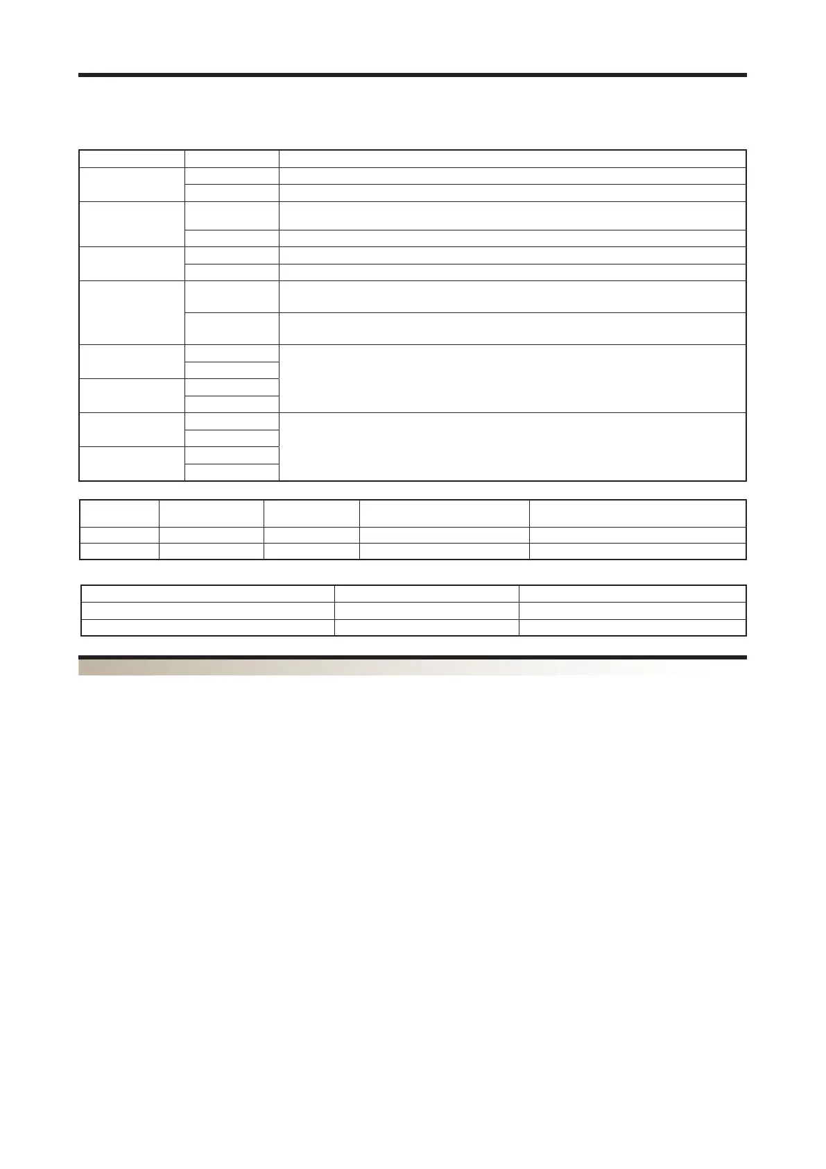
Dip_Board Meaning
Dip1
On
Dip2
On
Dip3
On Dead band 2°C
Dead band 5°C
Dip4
On
Dip5
On
See Table 2
(Type of system)
Dip6
On
Dip7
On
See Table 3
(Type of fan coil)
Dip8
On
Type of Sys-
tem
2-Pipe System with
4-pipe system
2-Pipe System with Plasma Clus-
ter/Bactericide lamp
2-pipe system Cold Only + Electric resistor
(2T+2F)
Dip5 OFF ON OFF ON
Dip6 OFF OFF ON ON
Type of fan coil ULI16C ULI26C ULI36C
Dip7 ON OFF
Dip8 OFF OFF
The board has specific configuration dip-switches for the possible installations. There are 8 microswitches are and they have the fol-
lowing functions:
 Loading...