52 U1241A/U1242A User’s and Service Guide
5 Performance Tests and Calibration
9 Turn the rotary switch to the next function according to the Test
Function column shown in Table 5- 14. Repeat steps 3 to 8 for each
adjustment point shown in the calibration adjustment, see Table 5- 15.
10 Verify the adjustments using the Performance Verification Tests.
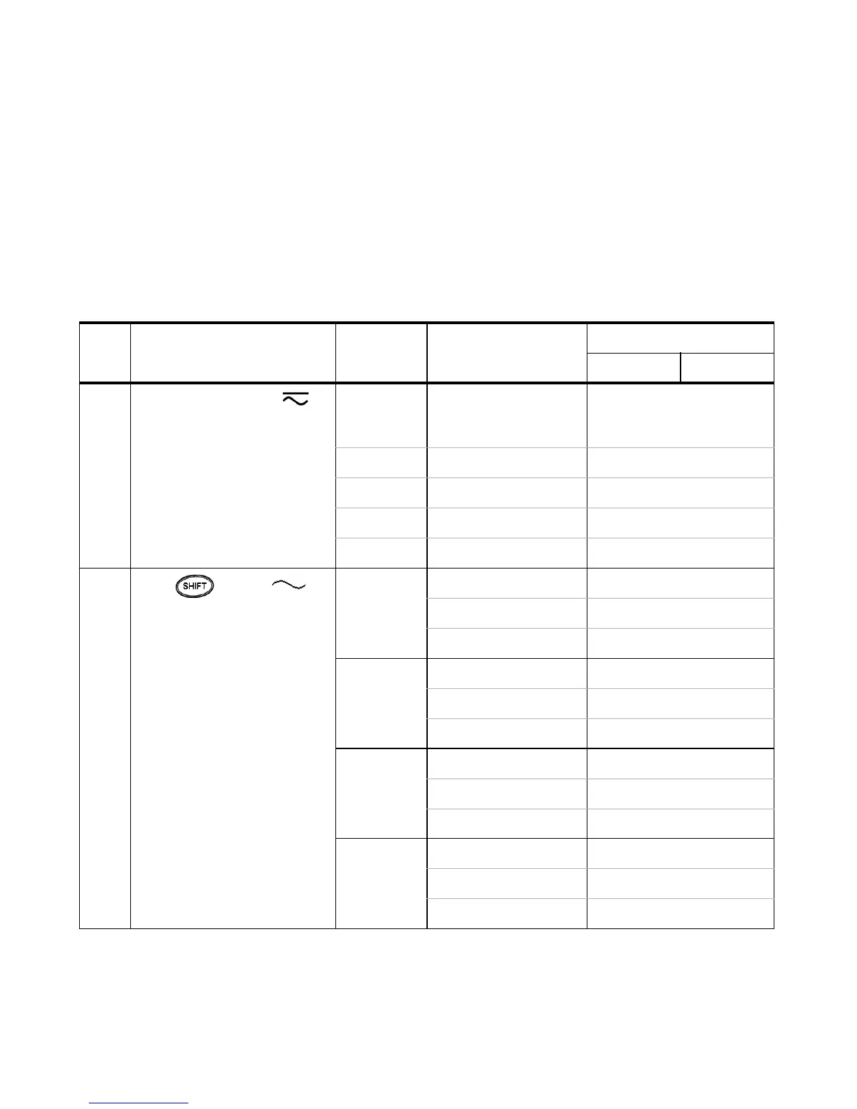
Table 5 - 15 Calibration Adjustments
Step Test Function Cal Range Input Reference Value Cal Item
U1241A U1242A
1 Turn the rotary switch to V
position
Short Dual banana plug with
copper wires short
between two terminals
SHrt
1000 mV 1 V 1000.0 mV
10 V 10 V 10.000 V
100 V 100 V 100.00 V
1000 V 1000 V 1000.0 V
2 Press to go to V 1000 mV 30 mV, 70 Hz 30.0 mV
function 1000 mV, 70 Hz 1000.0 mV
1000 mV, 1 kHz 1000.0 mV
10 V 1 V, 70 Hz 1.000 V
10 V, 70 Hz 10.000 V
10 V, 1 kHz 10.000 V
100 V 10 V, 70 Hz 10.00 V
100 V, 70 Hz 100.00 V
100 V, 1 kHz 100.00 V
1000 V 100 V, 70 Hz 100.0 V
1000 V, 70 Hz 1000.0 V
1000V, 1 kHz 1000.0 V

 Loading...


