32 Agilent U1251A/U1252A User’s and Service Guide
1 Getting Started Tutorial
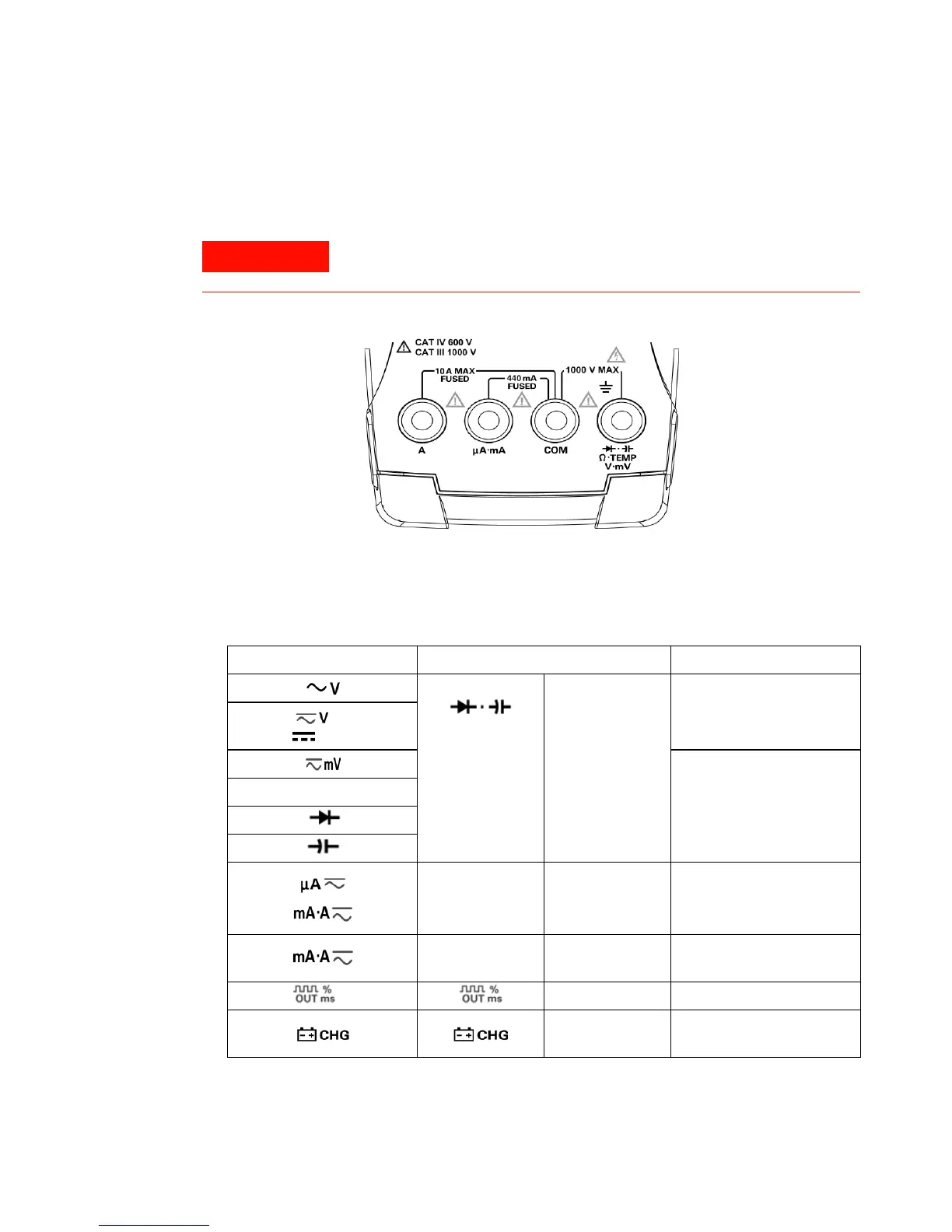
The Terminals at a Glance
Figure 1 U1252A Connector terminals
Tab l e 2 Terminal connections for different measuring functions
To avoid damaging this device, do not exceed the input limit.
Rotary switch position Input terminal Overload protection
V . mV . Ω .
.TEMP
COM 1000 V R.M.S.,
for U1252A
V for U1251A
1000 V R.M.S. for short circuit
<0.3 A
Ω
μA . mA COM 440 mA / 1000 V 30 kA
fast-acting fuse
A COM 11 A / 1000 V 30 kA
fast-acting fuse
for U1252A COM
COM 440 mA / 1000 V fast-acting
fuse

 Loading...


