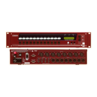
10 DR66 & DR128 Installer User Guide
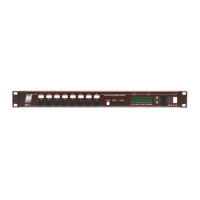
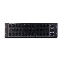
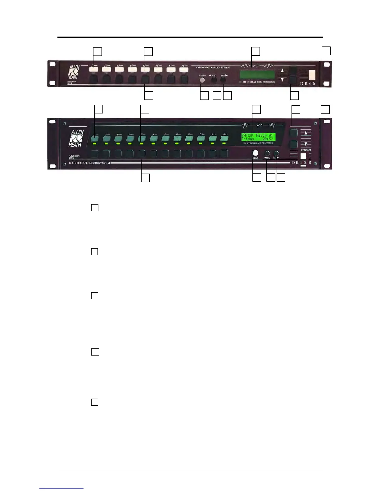
Front Panel
1 Ident Blocks Space is provided for writing on or adhering a label to identify the function of
the associated front panel key. The installer can remove the DR128 front panel plate so that the
label can be fitted behind the window. Do this by removing the four corner hex fixing screws. A
template with instructions is provided in this user guide and in electronic format with the WinDR
software.
2 Function Keys 8 Front panel function keys are provided on the DR66 and 12 on the DR128.
These can be assigned by the installer according to the requirements of the installation. They
would typically be assigned as level trim, channel mute, source select or patch change for day-to-
day operation. If they are not required they can simply be left unassigned. The key function can
change with patch recall if required.
3 Function LEDs Each function key has an associated 3-colour LED indicator. The LED can
be independently assigned as a 3-colour signal meter, or as a green, amber or red status indicator.
For example, it could be an input source meter with signal presence, 0dB and peak indicators for a
key assigned as an input volume control, or a red indicator for a mute key, patch active indicator,
or a colour coded source indicator with colour according to selected source patch. The LED
function does not need to be associated with that of the function key. It can also can change with
patch recall if required.
4 Display A 2x16 character illuminated LCD displays user information during day-to-day
operation, and installer information during setup. When switching the unit on it briefly displays the
boot code version number and then the operating software version number. During normal
operation it displays the current patch name (if loaded), current/last patch numbers as well as time
and day of week. It also momentarily displays channel name and level information when operating
function keys assigned as level controls. The display contrast can be adjusted in Setup mode.
5 SETUP Key Press and hold this key for at least 2 seconds to enter Setup mode. This mode
allows setup of some parameters from the front panel. The earlier V1.xx operating software
versions also allow password protected front panel control of matrix processor parameters and
patch recall. Version 2 restricts this to LCD contrast adjustment and time and day of week
changes while the enhanced parameter set is configured using the PC. The ◄ESC, SET►, ▲UP
and ▼DOWN keys are used to navigate and edit the Setup menus.
7 6 5 2
3
1
9
4
8
1
2
3
4
5 6 7
8 9
 Loading...