G
GG
GL
LL
L2
22
28
88
80
00
00
00
0M
MM
M
16
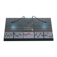
Allen & Heath
GL2800M Operating Tips
The following is a collection of brief application notes, hints and tips to
help the operator to get the most out of the uniquely capable
GL2
GL2GL2
GL28
88
800
0000
00M
MM
M live sound monitor mixing console. They are written as
a concise reference to spark your imagination to creatively and
effectively deal with the many challenges faced in modern day mixing.
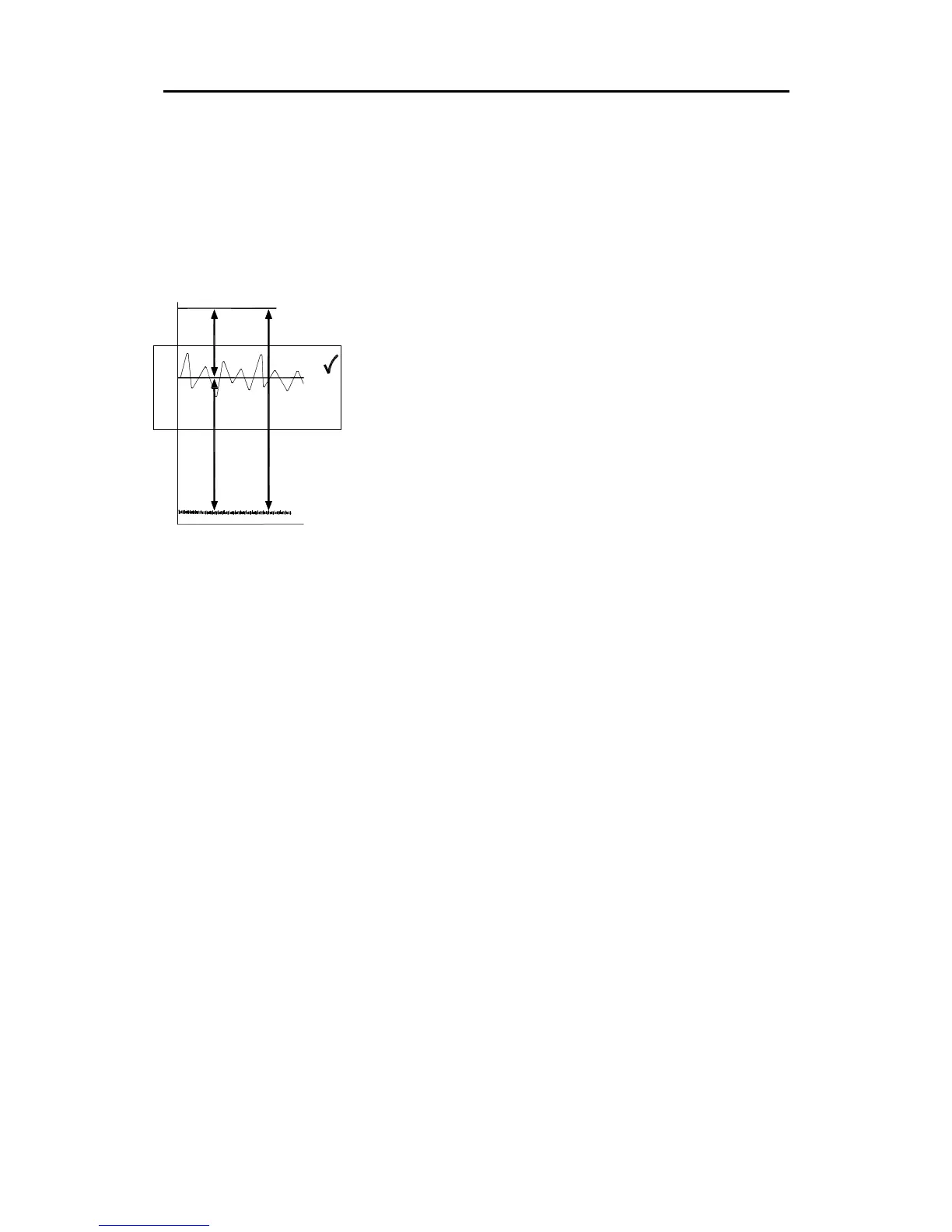
Gain Structure The term used to describe the gain (level)
matching of the signal through the audio system chain. Each item in
the equipment chain has its own optimum (‘nominal’) operating level
determined by its electrical circuits. If you overload it with a signal that
is too high then its output tries to produce more voltage than its power
rails can provide resulting in harsh sounding distortion as the audio
signal is ‘clipped’. If you work with a signal that is too low then you
are likely to hear the residual hiss of the circuits as the ‘noise floor’ is
amplified along with the signal. The optimum operating level is the
point at which the signal is high enough above the noise floor so that
the hiss is not heard (good ‘signal-to-noise’ ratio, the SNR), yet
provides enough space (‘headroom’) before clipping to allow for the
louder, dynamic musical moments without distortion. ‘Dynamic range’
specifies the maximum range between noise floor and clipping. It is
the sum of the SNR and headroom. The larger the figure the better…
less noise, more headroom, more forgiving to wide ranging signals.
A microphone produces a very tiny signal, for example -50dBu (a few
millivolts). This should be amplified by the channel preamp to the
optimum operating level of the console circuits, around 0dBu
(0.775V), well clear of the noise floor (typically less than -90dBu), and
with good headroom (typically clipping at greater than +20dBu). The
signal can pass through many stages which affect its level within the
console; the channel, its EQ, fader, pan, the mix head amp, inserted
EQ and processing, master fader, on to the main output. The output
XLR provides the professional standard +4dBu (1.23V) nominal level
to the next stage in the audio chain, typically a speaker processor
such as limiter or crossover, or straight to the amplifier. The amp
boosts this signal to tens of volts to move the speaker cones so
producing the audible sound.
To get the best performance from your system, it is important that you
set up the gain structure correctly within the console and also within
and between the connected equipment. Ideally, each circuit should
be set to clip at the same time if the signal became too hot, in other
words each would have similar headroom relative to its nominal
operating level. The resulting dynamic range is the difference
between the highest noise floor and the lowest headroom through the
system. The performance is only as good as the weakest link.
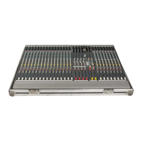
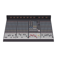
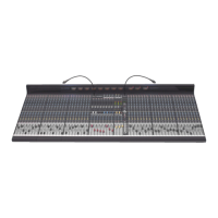
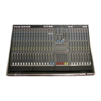
The GL2
GL2GL2
GL28
88
800
0000
00M
MM
M provides comprehensive metering to check every
point within the console signal path. Use the channel meters and
PFL/AFL system to set the gains and mix levels to average around ‘0’
meter reading with usual peaks around ‘+6’. Reduce the gain if the
red ‘+16’ or ‘PK’ indicator lights.
Use the equipment meters to set each item within the system path to
operate at its nominal level. We advise that the speaker processor or
amplifier trims are set so that the console outputs can drive up to their
nominal ‘0’ level. It is a common mistake to set amplifier trims to
maximum sensitivity when this results in the console master faders
being operated at very low positions, with low meter readings, and
reduced dynamic range and therefore audible residual system hiss.
+1
+3
+6
-12
-16
-9
-6
-3
-1
-20
0
+9
-30
-40
-50
-60
-70
-80
-90
+12
+16
+20
SIGNAL-TO-NOISE RATIO
DYNAMIC RANGE
HEADROOM
CLIPPING
NOISE
NORMAL OPERATING RANGE
SIGNAL
 Loading...