GR05 User Guide 11
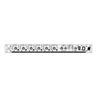
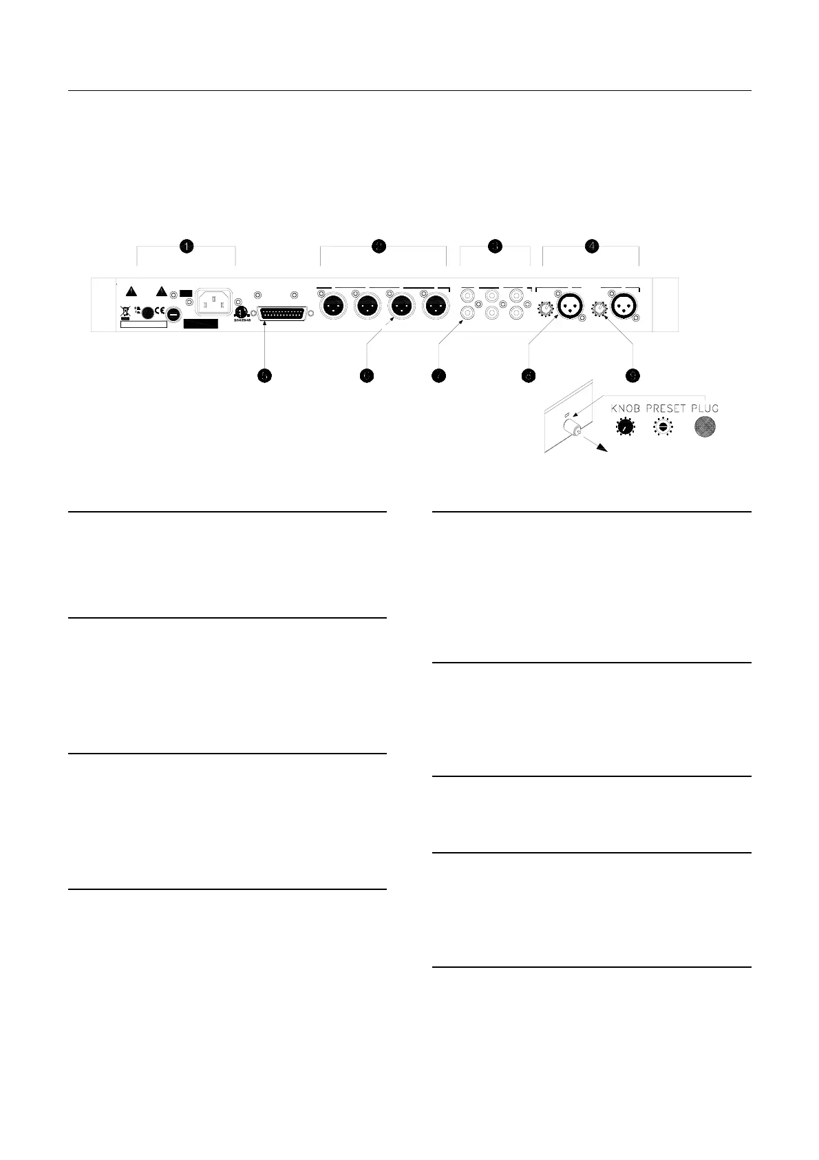
Rear Panel
The audio input and output connectors, expander/remote interface connector,
and mains input connector, fuse and switch are located on the rear panel. All
connections are pluggable to allow pre-wiring of the cables before the unit is
installed. The microphone input gain trimmers are also located on the rear to
allow easy readjustment of mic sensitivity by the installer but not the operator.
The factory set mains voltage and unit serial number are marked on the rear
panel.
Mains Input
Plug in the supplied IEC mains cable. Check that the
local mains voltage matches the voltage marked on the
rear panel. Press the switch to turn the power on or off.
The mains input fuse is accessible here.
Output Connectors
Each of the 4 outputs has a 3-pin male XLR connector.
This is impedance balanced to prevent interference
pickup on long cable runs. The outputs can feed both
balanced and unbalanced equipment. The operating
level is set between low –10dBV and high +4dBu by
adjusting internal trimmers.
Line Input 3,4,5 Connectors
These are dual RCA phono sockets to accept the Left
and Right signals of stereo sources. Most CD, tape and
background music equipment uses RCA type
connectors. Plug into either input for mono sources.
Sensitivity is set to low –10dBV or high +4dBu using
internal jumper links.
Microphone Input 1,2 Connectors
These inputs are electronically balanced on 3-pin female
XLR connectors wired pin2 hot. The input can be wired
for unbalanced sources. Phantom power can be
internally selected. For high output microphones or line
level sources set the internal jumper links for pad
selection. The sensitivity of the input stage is matched
to the microphone by adjusting the rear gain trimmer for
correct reading on the front signal meter.
Expander / Remote Connector
This 25-pin D-type female connector provides a set of
inputs and outputs for system expansion and special
functions such as alarm interface. Also accessible are
the output level remote control inputs together with a
+10V DC reference and the opto-isolated external
ducking trigger input. The pin configuration is marked
on the top cover.
Output XLR Connector
3-pin male impedance balanced XLR connector.
Pin 1 = 0V ground
Pin 2 = Signal + (hot)
Pin 3 = Signal – (cold)
Line Input RCA Connector
Standard pin type RCA phono connector for unbalanced
connection.
Input XLR Connector
3-pin female electronically balanced XLR connector.
Pin 1 = 0V ground
Pin 2 = Signal + (hot)
Pin 3 = Signal – (cold)
Microphone Gain Trimmer
Sets the gain of the microphone pre-amplifier. This
control can be set as a preset or locked out after
adjustment.
S/No
18W MAX
47-63Hz~ V.AC
ATTENTI ON: REMPLACER PAR UN FUSIBLE STRICT EMENT IDENTIQUE EN VALEURS.
FOR CONTINUED PROTECTION AGAINST RISK O F FIRE REPLACE FUSE WITH SAM E TYPE AND RATING.
CONFORMS TO UL STD. 6500
CERTIFICATED TO CAN/CSA STD. E60065
EXPANDER / REMOTE
ALLEN&HEATH
GR05
100-120V ~ = T630mAL 250V 20mm
220-240V ~ = T315mAL 250V 20mm
FUSE
CAUTION: RISK O F ELECTRIC SHOCK. HIGH VOLTA GE INSIDE.
AVIS: RI SQUE DE CHOC ELECTRIQUE
WARNING
THIS APPARATUS MUST BE EARTHED.
MIN
L
R
3
MAX
GAIN GAIN
MAX
2 MIC/LINE IN
MIN
14
OUT
LINE 3
MADE IN THE UK BY AL LEN & HEATH LIMITED
2 1
IN
LINE
L
R
5
L
R
4
 Loading...