GR05 User Guide 17
Remote Control
This section describes the installer configuration of the VCA path remote level
control. For each output you can select whether the level is controlled by the
front panel control or by remote DC voltage. Note that this does not affect
signals which are routed through the DIRECT path to the outputs.
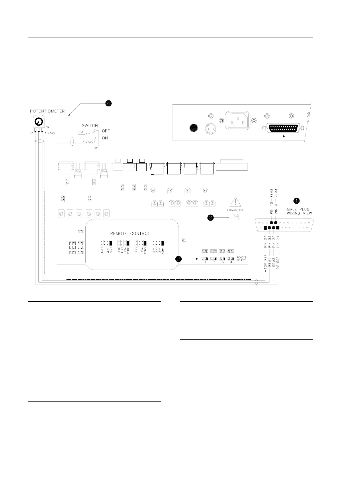
To configure the unit switch off power, remove the top cover and adjust the
jumper links as shown. Avoid the power supply components shown greyed out
on the diagram.
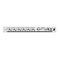
The Remote Connector
The expander / remote 25-pin D-type female connector
includes a remote DC input for each of the 4 outputs to
control the level. A buffered +10V.DC reference voltage
and 0V ground is provided so that external
potentiometers or switches may be used to remotely
control the levels. Use screened wire to shield these
control signals from interference.
Pin 24 = +10V.DC reference
Pin 21 = 0V ground
Pin 23 = Remote input 1
Pin 10 = Remote input 2
Pin 22 = Remote input 3
Pin 9 = Remote input 4
Remote Select
For each output to be remote controlled set the link to
REM(1,2,3,4) as shown. Note that signals routed to the
output via the DIRECT path will not be affected by the
remote control.
+10V.DC Reference
This internal trimmer sets the reference voltage. This
has been factory set and should not normally need to be
adjusted.
The Remote Controller
The simplest form of remote controller is a potentiometer
or switch wired from the reference +10V and 0V ground.
The recommended potentiometer is 10k ohm with a
reverse logarithmic law. Connect with screened cable.
Signal off = 0V (ground)
Signal on max = +10V.DC
Alternatively you can connect any external system
controller that provides a 0 to +10V.DC control line.
Do not connect any signal or voltage other than the
specified 0 to +10V.DC to these inputs.
EXPANDER / REMOTE
 Loading...