2 Compact 1769-OF8C Analog Output Module
Publication 1769-IN065B-EN-P - September 2005
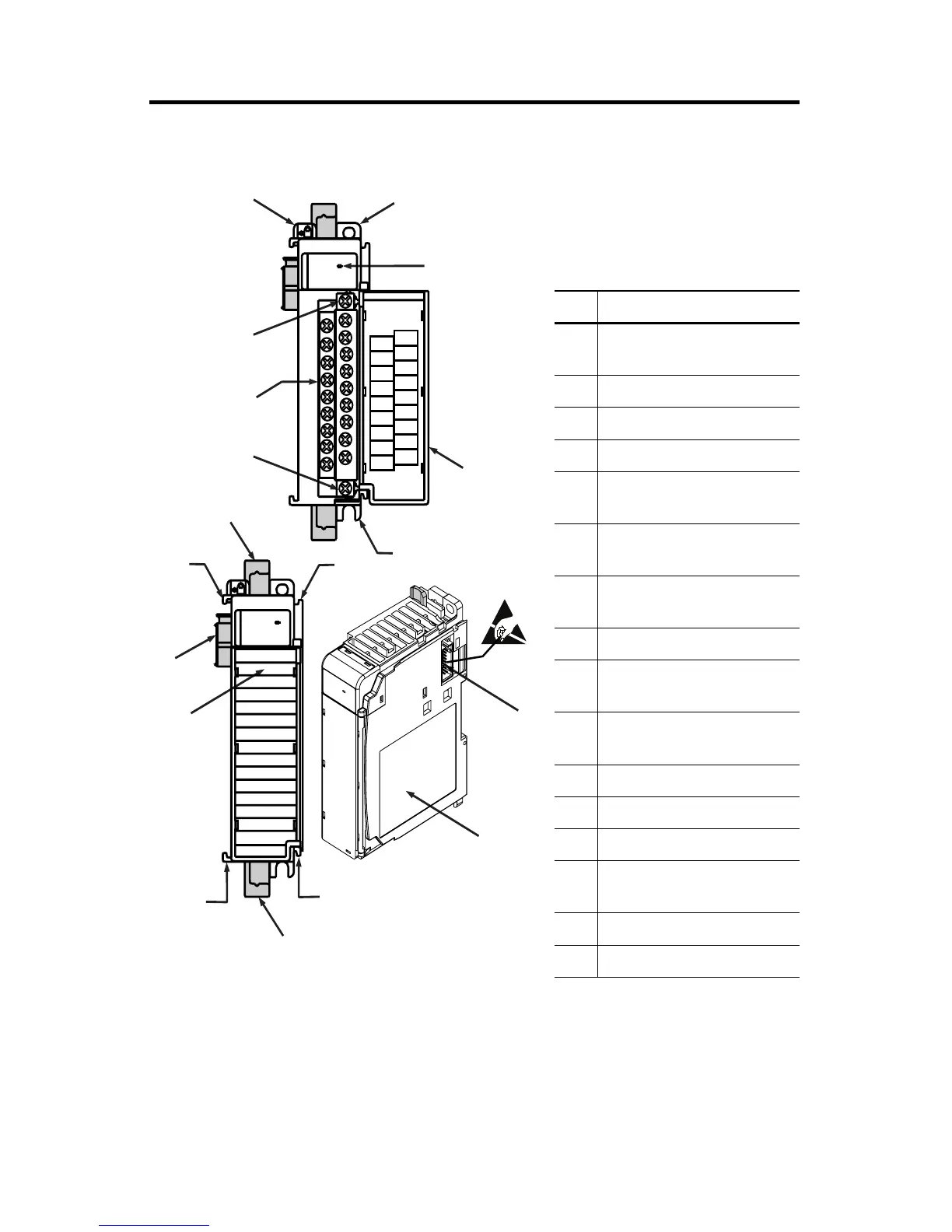
Module Description
Item Description
1 bus lever
(with locking function)
2a upper panel mounting tab
2b lower panel mounting tab
3 module status LED
4 module door with terminal
identification label
5a movable bus connector
with female pins
5b stationary bus connector
with male pins
6 nameplate label
7a upper
tongue-and-groove slots
7b lower
tongue-and-groove slots
8a upper DIN rail latch
8b lower DIN rail latch
9 write-on label (user ID tag)
10 removable terminal block (RTB)
with finger-safe cover
10a RTB upper retaining screw
10b RTB lower retaining screw
10a
10b
4
10
2b
3
6
7a
7b
8b
7b
8a
7a
1769-OF8C
DANGER
Do Not Remove RTB Under Power
Unless Area is Non-Hazardous
Ensure Adjacent
Bus Lever is Unlatched/Latched
Before/After
Removing/Inserting Module
dc
NEUT
I out 2 +
I out 3 +
I out 4 +
I out 5 +
I out 6 +
I out 7 +
+24V dc
I out 1 +
I out 0 +
ANGL
Com
ANLG
Com
ANLG
Com
ANLG
Com
ANLG
Com
ANLG
Com
ANLG
Com
ANLG
Com
OK
Analog
OK
Analog

 Loading...


