12 Compact 1769-OF8C Analog Output Module
Publication 1769-IN065B-EN-P - September 2005
Wire Size and Terminal Screw Torque
Each terminal accepts up to two wires with the following restrictions:
I/O Memory Mapping
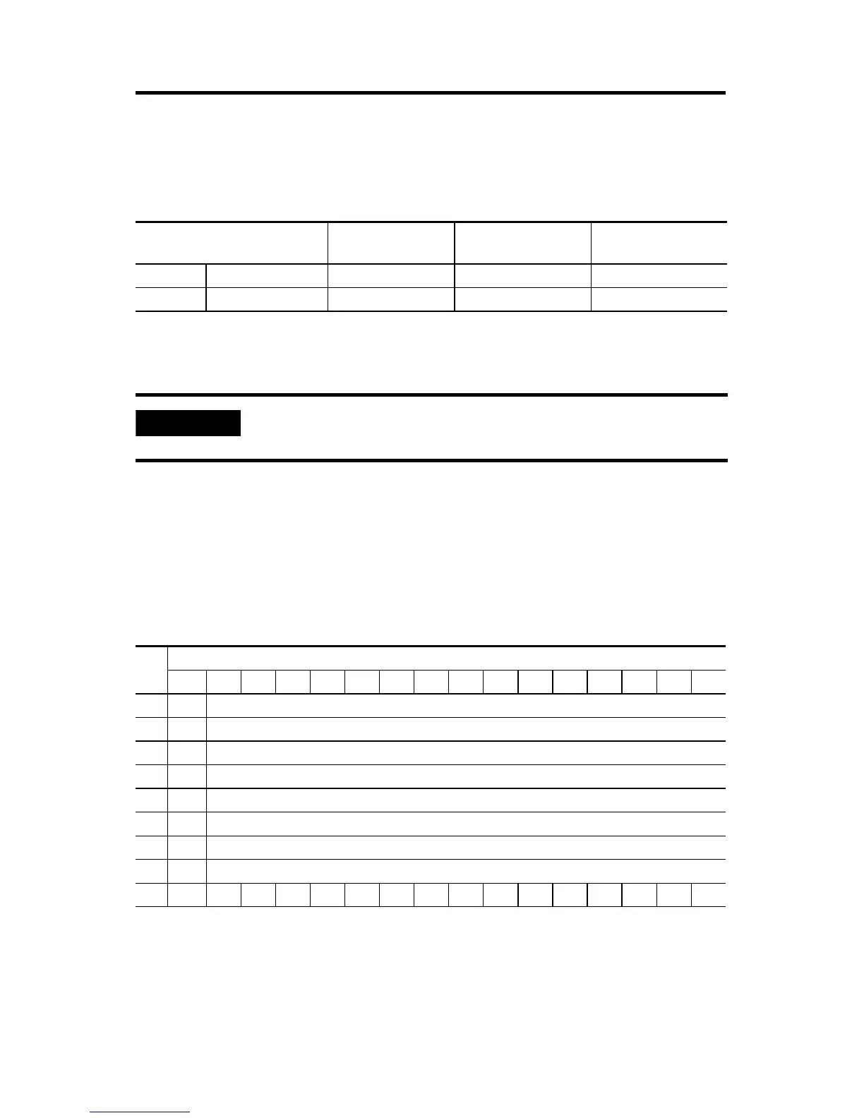
Output Data File
For each module, slot x, words 0-7 in the output data file contain the channel 0
through 7 output data. Word 8 is used to unlatch any condition that has been
latched. Refer to the Compact™ Analog I/O User Manual, publication number
1769-UM002 for additional details.
• SGN = Sign bit in two’s complement format.
• UU = Unlatch under-range (or low clamp exceeded) alarm.
• UO = Unlatch over-range (or high clamp exceeded) alarm.
Wire Type Wire Size Terminal Screw
Torque
Retaining Screw
Torque
Solid Cu-90°C (194°F) #14 to #22 AWG 0.68 Nm (6 in-lbs) 0.46 Nm (4.1 in-lbs)
Stranded Cu-90°C (194°F) #16 to #22 AWG 0.68 Nm (6 in-lbs) 0.46 Nm (4.1 in-lbs)
IMPORTANT
If you are using RSLogix 5000, version 15, please refer to RSLogix
5000, Version 15, Controller Tags on page 17.
Word
Bit Position
15 14 13 12 11 10 9 8 7 6 5 4 3 2 1 0
0 SGN Analog Output Data Channel 0
1 SGN Analog Output Data Channel 1
2 SGN Analog Output Data Channel 2
3 SGN Analog Output Data Channel 3
4 SGN Analog Output Data Channel 4
5 SGN Analog Output Data Channel 5
6 SGN Analog Output Data Channel 6
7 SGN Analog Output Data Channel 7
8 UU7 UO7 UU6 UO6 UU5 UO5 UU4 UO4 UU3 UO3 UU2 UO2 UU1 UO1 UU0 UO0

 Loading...


