Compact 1769-OF8C Analog Output Module 11
Publication 1769-IN065B-EN-P - September 2005
Removing the Finger-Safe Terminal Block
To remove the terminal block, loosen the upper and lower retaining screws. The
terminal block will back away from the module as you remove the screws. When
replacing the terminal block, torque the retaining screws to 0.46 Nm (4.1 in-lbs).
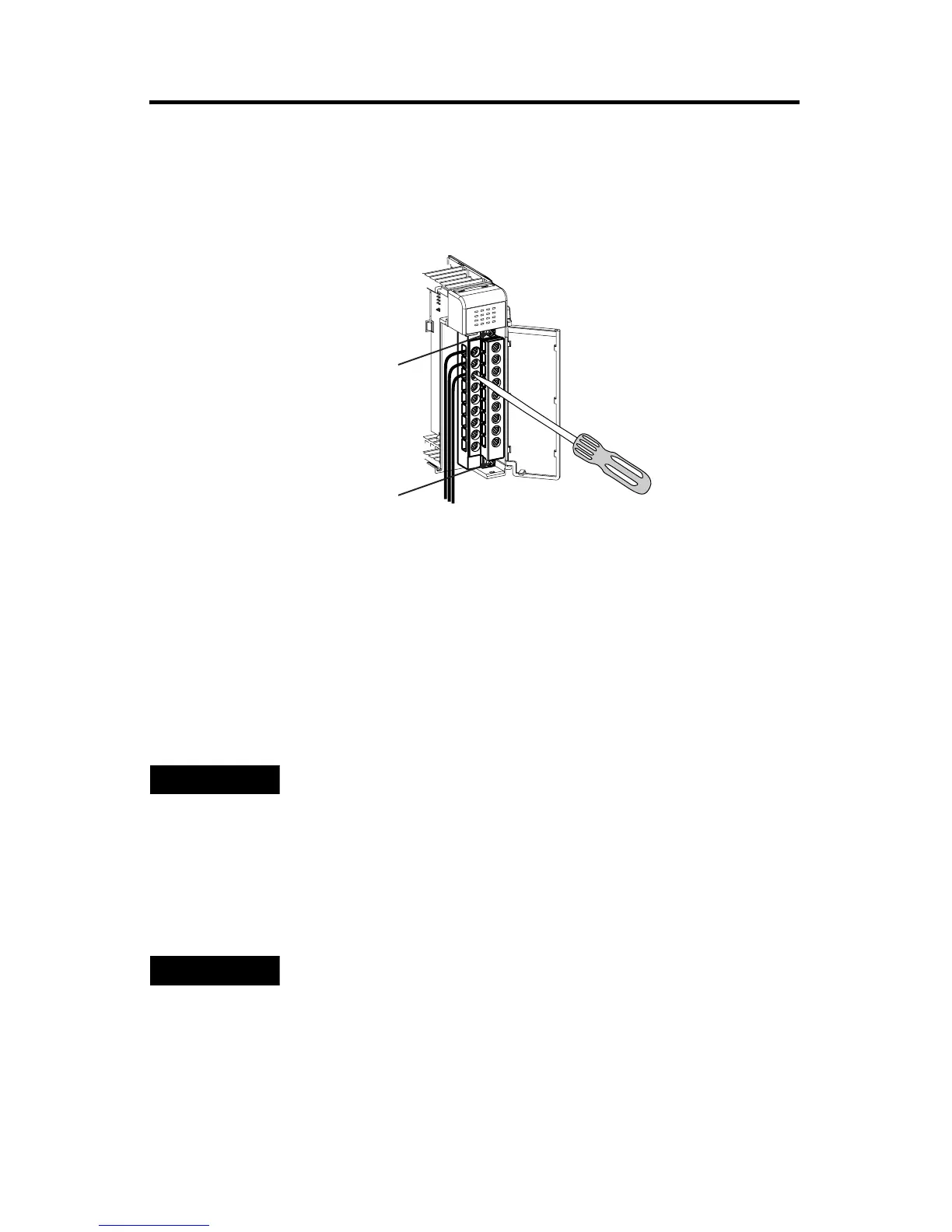
Wiring the Finger-Safe Terminal Block
When wiring the terminal block, keep the finger-safe cover in place.
1. Loosen the terminal screws to be wired.
2. Route the wire under the terminal pressure plate. You can use the bare wire
or a spade lug. The terminals will accept a 6.35 mm (0.25 in.) spade lug.
3. Tighten the terminal screw making sure the pressure plate secures the wire.
Recommended torque when tightening terminal screws is 0.68 Nm (6 in-lbs).
TIP
The terminal screws are non-captive. Therefore, it is possible to
use a ring lug [maximum 1/4 inch o.d. with a 0.139 inch
minimum i.d. (M3.5)] with the module.
TIP
If you need to remove the finger-safe cover, insert a screw
driver into one of the square, wiring holes and gently pry the
cover off. If you wire the terminal block with the finger-safe
cover removed, you will not be able to put it back on the
terminal block because the wires will be in the way.
wiring the
finger-safe
terminal block
upper retaining screw
lower retaining screw

 Loading...


