14 Rockwell Automation Publication 1769-IN028C-EN-P - August 2016
Compact I/O Expansion Power Supplies
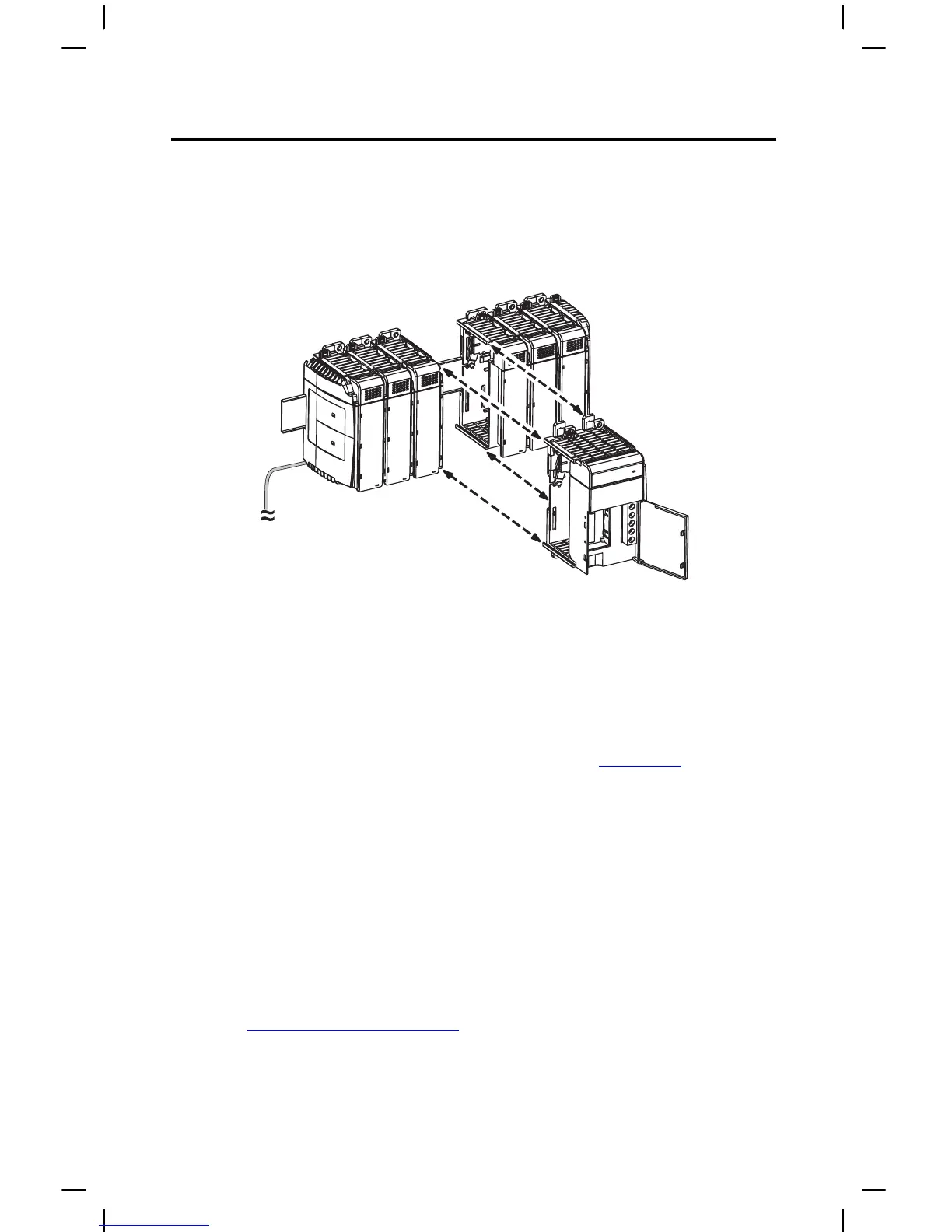
2. Press the DIN rail mounting area of the module against the DIN rail.
The latches momentarily open and lock into place. The following illustration shows a
power supply being attached to the I/O modules in a DIN rail mounted Compact I/O
system.
Verify Your System Power
Your system power budget is a consideration when using 1769 power supplies. This budget
determines the power that is being provided to the I/O modules. See Power Supply Distance
Ratings in the CompactLogix™ System Selection Guide, publication 1769-SG001, for the power
requirements.
1. After you have reviewed the amount of current consumed by your system, verify that
your power supply has adequate capacity for its bank of I/O modules.
See Temp er a tur e D er a t i n g
on page 25 for graphs.
2. To do so, compare the current graphs to your totals for the following:
•Total 5V DC
• Total 24V DC
TIP The total number of I/O modules cannot exceed 16 on one bank with a maximum of 8 I/O
modules on either side of the power supply.
You system can be used in a maximum of two banks of I/O modules. This condition occurs
when you configure your system with a MicroLogix™ 1500 controller, one expansion cable,
one expansion power supply, and a total of eight I/O modules. The expansion power supply
cannot be directly connected to the MicroLogix 1500 controller.
 Loading...