Rockwell Automation Publication 22C-UM001J-EN-E - January 2017 159
Application Notes Appendix D
Trim Control
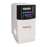
In Trim Control, the PID Output is added to the Speed Reference. In Trim
mode, the output of the PID loop bypasses the accel/decel ramp as shown.
Trim Control is used when A152
[PID Ref Sel] is set to option 5, 6, 7 or 8.
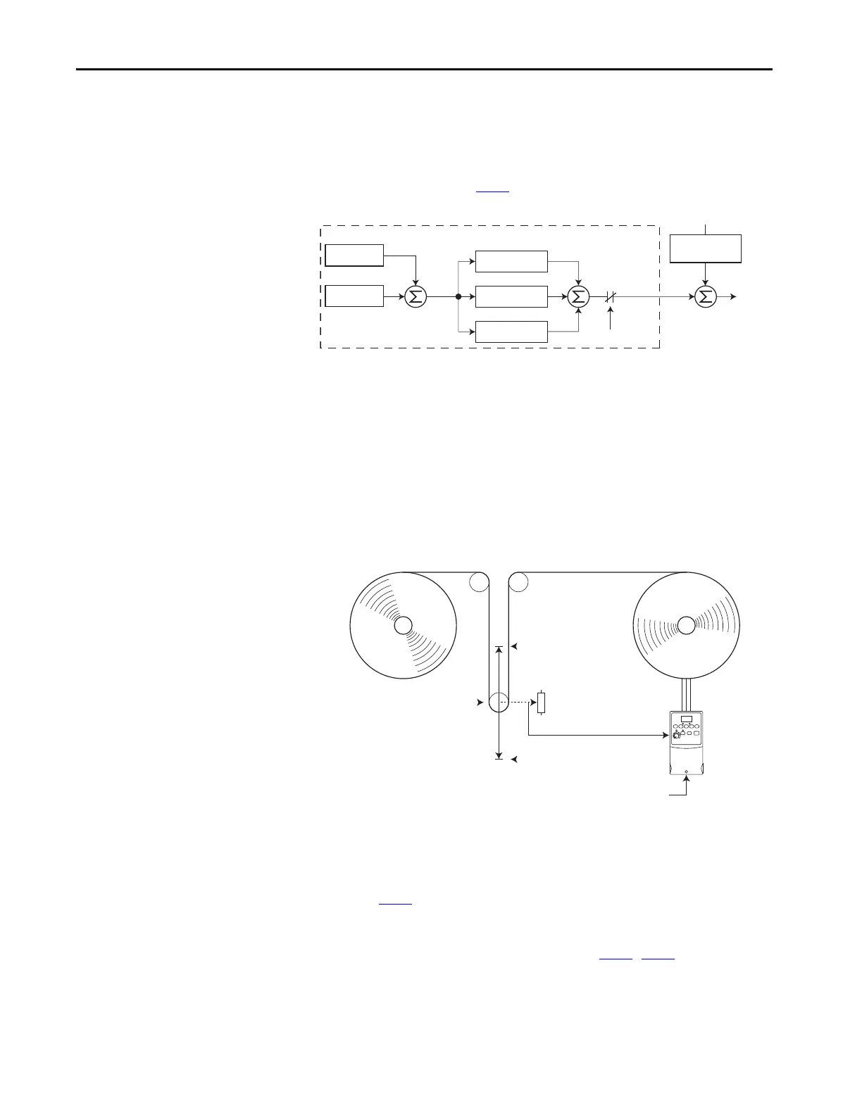
Example
• In a winder application, the PID Reference equals the Equilibrium
set point.
• The Dancer Pot signal provides PID Feedback to the drive.
Fluctuations in tension result in a PID Error value.
• The Master Speed Reference sets the wind/unwind speed.
• As tension increases or decreases during winding, the Speed Reference is
trimmed to compensate. Tension is maintained near the Equilibrium
set point.
PID Reference and Feedback
Parameter A152 [PID Ref Sel] is used to enable the PID mode (A152 = 0
“PID Disabled”) and to select the source of the PID Reference. If A152 [PID
Ref Sel] is not set to 0 “PID Disabled”, PID can still be disabled by select
programmable digital input options (parameters T051
...T054) such as “Local”
or “PID Disable”.
–
+
PID Prop Gain
PID Loop
PID Integ Time
PID Diff Rate
PID Enabled
Speed Ref
PID Fdbk
PID Ref
PID
Error
+
+
+
+
PID
Output
Output
Freq
+
Accel/Decel
Ramp
Speed Reference
0 Volts
PID Feedback =
Dancer Pot Signal
10 Volts
PID Reference =
Equilibrium Set Point
 Loading...