42 Rockwell Automation Publication 5069-UM003A-EN-P - May 2018
Chapter 3 Compact 5000 I/O Serial Module Features
Modbus Slave Functions
For Modbus Master and Modbus Slave Sample code, see page 104.
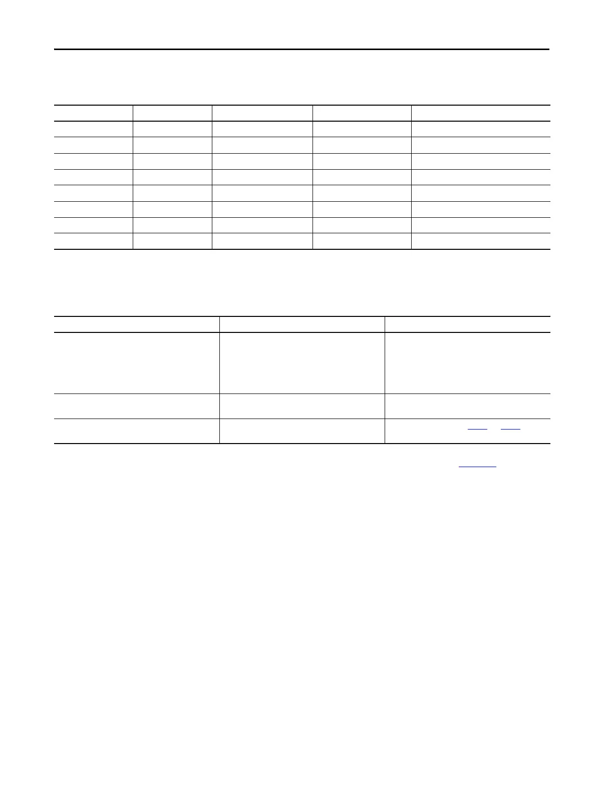
Table 9 - Inter-frame Timeout Minimum Values (11 Bit)
Baud Rate Default Value 1Byte (11Bit) 3.5t (11Bit) Legal Range (11Bit)
1200 64000 9166.667 32083.333 32000…65535000 (us)
2400 32000 4583.333 16041.667 16000…65535000 (us)
4800 16000 2291.667 8020.833 8000…65535000 (us)
9600 8000 1145.833 4010.417 4000…65535000 (us)
19200 3500 572.917 2005.208 1750…65535000 (us)
38400 3500 286.458 1002.604 1750…65535000 (us)
57600 3500 190.972 668.403 1750…65535000 (us)
115200 3500 95.486 334.201 1750…65535000 (us)
Table 10 - Modbus Slave Configuration Parameters
Parameter Definition Available Options
Modbus Format Selecting communication method of Modbus of each
channel.
•0 = RTU (default)
•1 = ASCII
– Intervals of up to one second may elapse between
characters within the message. Unless the user has
configured a longer timeout, an interval greater
than 1 second means an error has occurred.
Node Address Numbers to identify all modules that are connected to
each channel. You must set a number not equal to 0.
• 1…247
(default = 1)
Inter-frame Timeout Maximum delay time to receive Data of each channel • 0 is not a valid value. Use Table 8
and Tab le 9 to
determine the minimum value.
 Loading...


