10 MicroLogix 1200 Analog Output Module
Publication 1762-IN016B-EN-P - December 2005
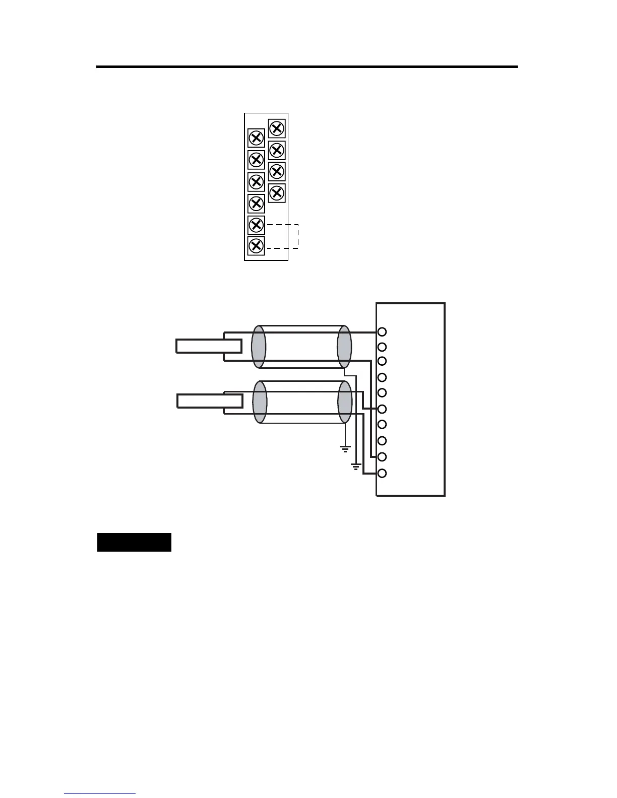
Figure 5 Terminal Block Layout
Figure 6 Differential Sensor Transmitter Types
A write-on label is provided with the module. Mark the identification of each
terminal with permanent ink, and slide the label back into the door.
Ground the Module
This product is intended to be mounted to a well-grounded mounting surface such
as a metal panel. Additional grounding connections from the module’s mounting
tabs or DIN rail (if used) are not required unless the mounting surface cannot be
TIP
Grounding the cable shield at the module end only usually
provides sufficient noise immunity. However, for best cable shield
performance, earth ground the shield at both ends, using a 0.01
µF capacitor at one end to block AC power ground currents, if
necessary.
V out 3
V out 2
V out 1
V out 0
I out 3
I out 2
I out 1
I out 0
COM
COM
Commons connected
internally.
I out 0
I out 1
V out 2
V out 3
V out 0
V out 1
COM
I out 3
I out 2
COM
Current Load
Voltage Load

 Loading...


