12 MicroLogix 1200 Analog Output Module
Publication 1762-IN016B-EN-P - December 2005
Wire Size and Terminal Screw Torque
Each terminal accepts up to two wires with the following restrictions:
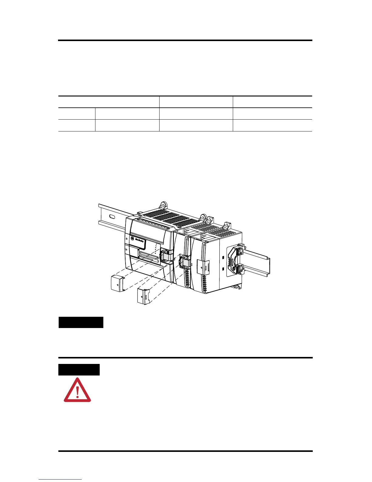
System Assembly
The expansion I/O module is attached to the controller or another I/O module by
means of a ribbon cable after mounting as shown below.
Figure 8 Ribbon Cable Connection
Wire Type Wire Size Terminal Screw Torque
Solid Cu-90 °C (194 °F) #14 to #22 AWG 0.904 Nm (8 in-lbs)
Stranded Cu-90 °C (194 °F) #16 to #22 AWG 0.904 Nm (8 in-lbs)
TIP
Use the pull loop on the connector to disconnect modules. Do
not pull on the ribbon cable.
ATTENTION
EXPLOSION HAZARD
• In Class I, Division 2 applications, the bus connector must be
fully seated and the bus connector cover must be snapped in
place.
• In Class I, Division 2 applications, all modules must be
mounted in direct contact with each other as shown on
page 7. If DIN rail mounting is used, an end stop must be
installed ahead of the controller and after the last 1762 I/O
module.

 Loading...


