MicroLogix 1200 Analog Output Module 9
Publication 1762-IN016B-EN-P - December 2005
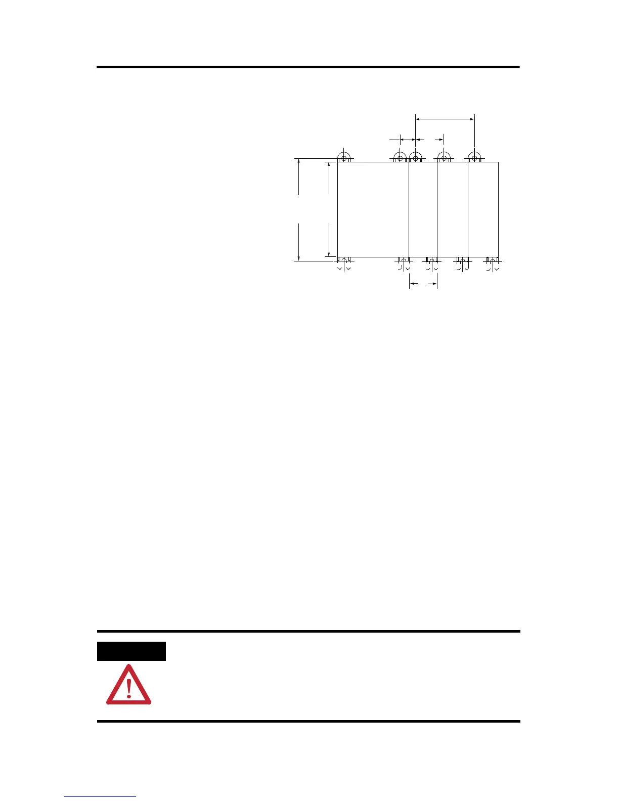
Figure 4 Dimensional Template
Wire the Analog Output Module
The output type selection, current or voltage, is made by wiring to the appropriate
terminals, Iout or Vout, and by the type/range selection bits in the Configuration
Data File (see page 14).
Consider the following when wiring your system:
• The analog common (COM) is not connected to earth ground inside the
module. All terminals are electrically isolated from the system.
• Channels are not isolated from each other.
• Use Belden 8761, or equivalent, shielded wire.
• Under normal conditions, the drain wire (shield) should be connected to the
metal mounting panel (earth ground). Keep shield connection to earth
ground as short as possible.
• To ensure optimum accuracy for voltage type outputs, limit overall cable
impedance by keeping all analog cables as short as possible. Locate the I/O
system as close to your voltage type sensors or actuators as possible.
ATTENTION
Analog outputs may fluctuate for less than a second when power
is applied or removed. This characteristic is common to most
analog outputs. While the majority of loads will not recognize this
short signal, it is recommended that preventive measures be taken
to ensure that connected equipment is not affected.
90
(3.54)
100
(3.94)
40.4
(1.59)
40.4
(1.59)
14.5
(0.57)
For more than 2 modules: (number of modules - 1) x 40.4 mm (1.59 in.)
NOTE:
Hole spacing tolerance:
±0.4 mm (0.016 in.).
MicroLogix 1200
Expansion I/O
MicroLogix 1200
Expansion I/O
MicroLogix 1200
Expansion I/O
MicroLogix 1200

 Loading...


