EasyManuals Logo
Home>Allen-Bradley>Control Unit>MicroLogix 1762-IF4

Allen-Bradley MicroLogix 1762-IF4 User Manual

Allen-Bradley MicroLogix 1762-IF4
23 pages
To Next Page IconTo Next Page
To Previous Page IconTo Previous Page
Page #12 background imageLoading...
Page #12 background image
12 MicroLogix 1762-IF4 Analog Input Module
Publication 1762-IN012C-EN-P - June 2013
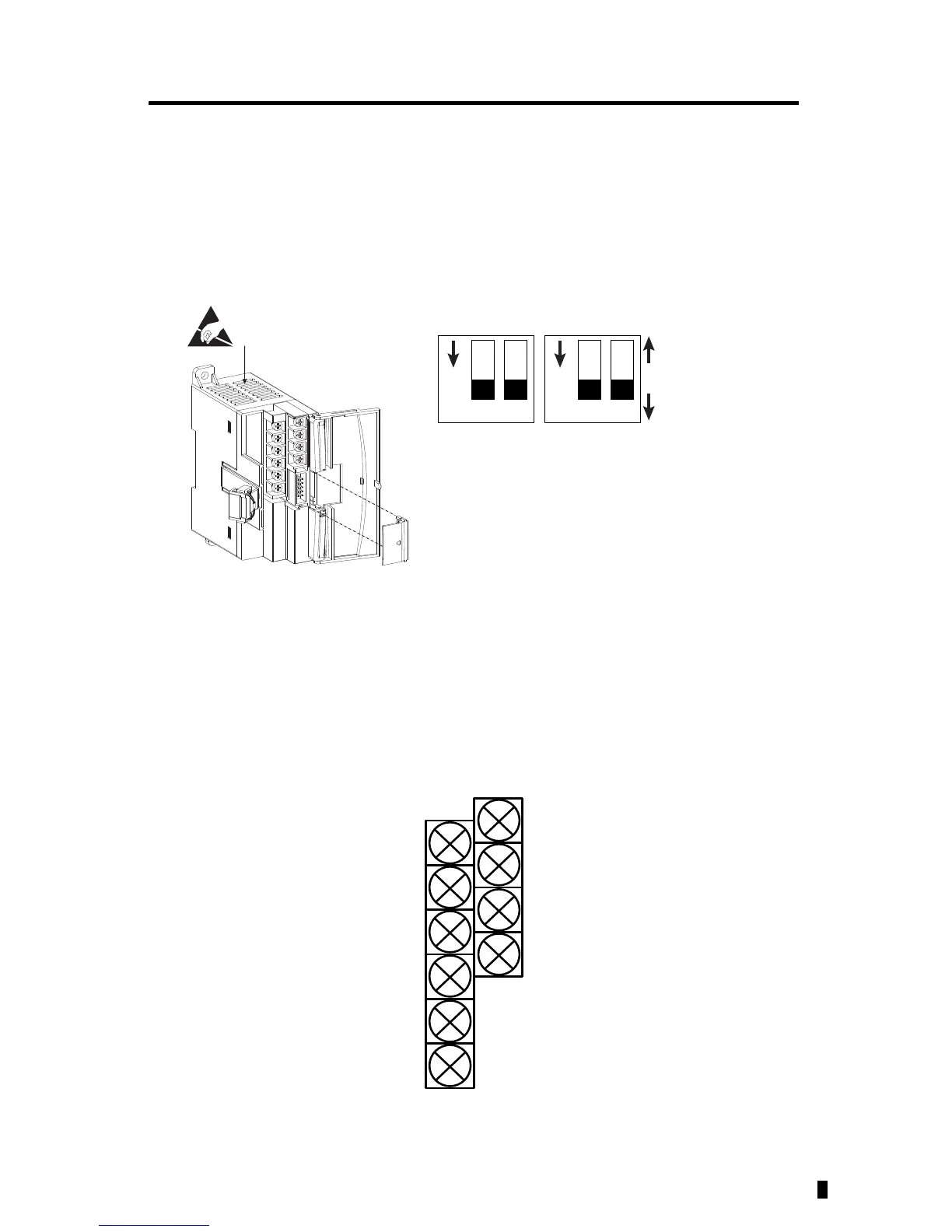
Input Type Selection
Select the input type, current or voltage, using the switch located on the module’s circuit board
and the input type/range selection bits in the Configuration Data File (see page 17). You can
access the switch through the ventilation slots on the top of the module. The factory default
setting for all switches is Current. Switch positions are shown below.
Input Wiring
Basic wiring of input devices to the 1762-IF4 is shown below.
Terminal Block Layout
1
Ch0 Ch1 Ch2 Ch3
ON
2 1
ON
2
Current (ON) Default
Voltage (OFF)
Switch Location
45162
IN0 -
IN1 -
IN2 -
IN3 -
IN0 +
IN1 +
IN2 +
IN3 +
COM
COM
Commons connected
internally

Questions and Answers:

Question and Answer IconNeed help?

Do you have a question about the Allen-Bradley MicroLogix 1762-IF4 and is the answer not in the manual?

Allen-Bradley MicroLogix 1762-IF4 Specifications

General IconGeneral
BrandAllen-Bradley
ModelMicroLogix 1762-IF4
CategoryControl Unit
LanguageEnglish

Related product manuals