MicroLogix 1762-IF4 Analog Input Module 15
Publication 1762-IN012C-EN-P - June 2013
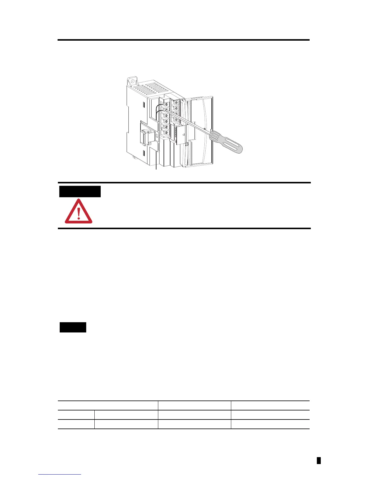
Wiring the Finger-Safe Terminal Block
When wiring the terminal block, keep the finger-safe cover in place.
1. Route the wire under the terminal pressure plate. You can use the stripped end of the
wire or a spade lug. The terminals will accept a 6.35 mm (0.25 in.) spade lug.
2. Tighten the terminal screw making sure the pressure plate secures the wire.
Recommended torque when tightening terminal screws is 0.904 Nm (8 lb-in.).
3. After wiring is complete, remove the debris shield.
Wire Size and Terminal Screw Torque
Each terminal accepts up to two wires with the following restrictions:
Be careful when stripping wires. Wire fragments that fall into a module could
cause damage when power is applied. Once wiring is complete, ensure the
module is free of all metal fragments.
If you need to remove the finger-safe cover, insert a screw driver into one of the
square wiring holes and gently pry the cover off. If you wire the terminal block with
the finger-safe cover removed, you will not be able to put it back on the terminal
block because the wires will be in the way.
Wire Type Wire Size Terminal Screw Torque
Solid Cu-90 °C (194 °F) #14…22 AWG 0.904 Nm (8 lb-in.)
Stranded Cu-90 °C (194 °F) #16…22 AWG 0.904 Nm (8 lb-in.)

 Loading...


