MicroLogix 1762-IF4 Analog Input Module 7
Publication 1762-IN012C-EN-P - June 2013
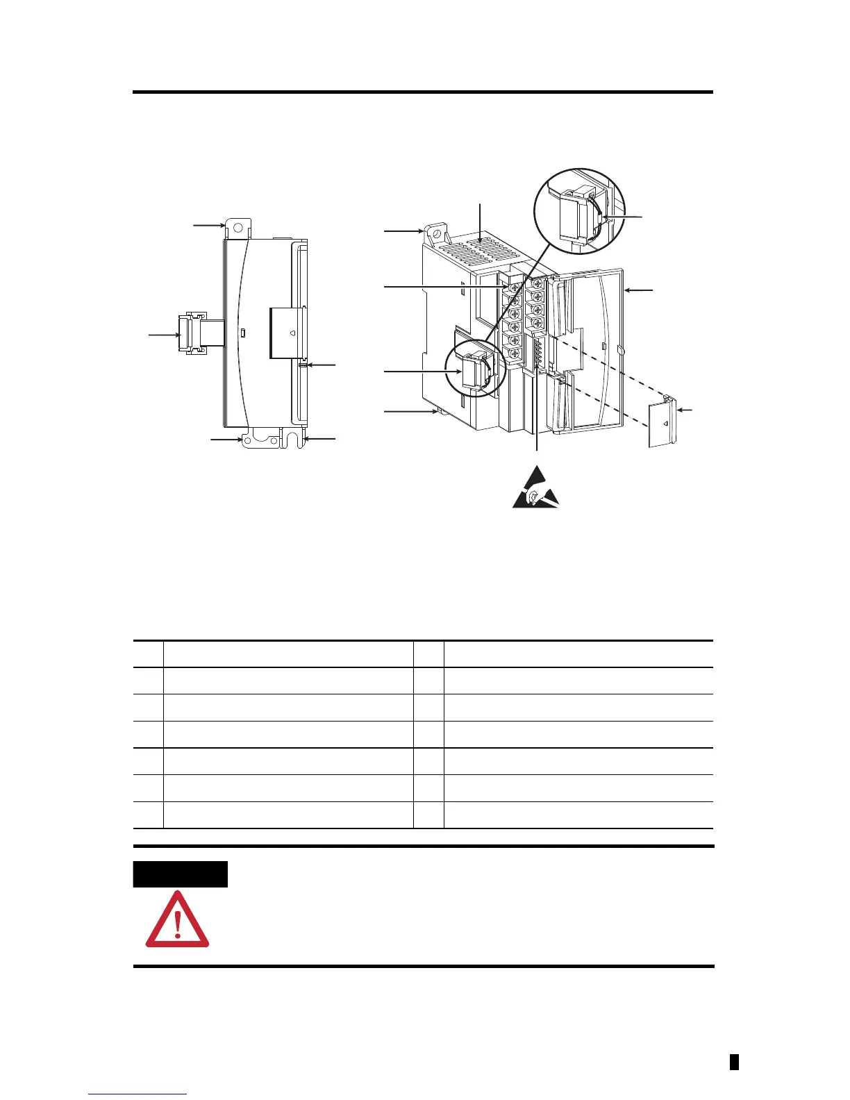
Module Description
Description Description
1a upper panel mounting tab 6 pull loop
1b lower panel mounting tab 7 module door with terminal identification label
2 power diagnostic LED 8 bus connector cover
3 flat ribbon cable with bus connector (female) 9 bus connector with male pins
4 DIN rail latch 10 terminal block
5 input type selector switch
To comply with UL restrictions, this equipment must be powered from a source
compliant with Class 2 or Limited Voltage/Current.
Left side view
Front view
This equipment is sensitive to electrostatic discharge (ESD).
Follow ESD prevention guidelines when handling this equipment.
45157

 Loading...


