8 MicroLogix 1762-IF4 Analog Input Module
Publication 1762-IN012C-EN-P - June 2013
Mount the Module
General Considerations
Most applications require installation in an industrial enclosure to reduce the effects of electrical
interference and environmental exposure. Locate your controller as far as possible from power
lines, load lines, and other sources of electrical noise such as hard-contact switches, relays, and
AC motor drives. For more information on proper grounding guidelines, see the Industrial
Automation Wiring and Grounding Guidelines, publication 1770-4.1
.
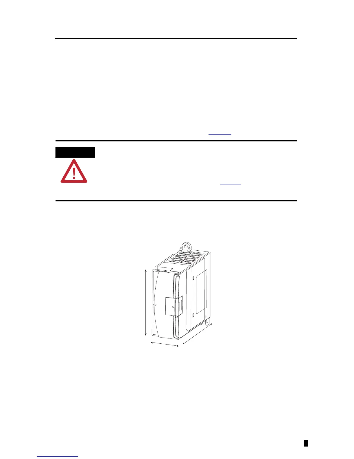
Mounting Dimensions
This product is intended to be mounted to a well-grounded mounting surface
such as a metal panel. Additional grounding connections from the power
supply's mounting tabs or DIN rail (if used) are not required unless the mounting
surface cannot be grounded. Refer to Industrial Automation Wiring and
Grounding Guidelines, Allen-Bradley publication 1770-4.1
, for additional
information.

 Loading...


