Publication 2711P-UM001A-EN-P
Installing and Replacing Components 5-5
Installing/Replacing a
Communication Module
This section shows how to install and replace a Communication
Module on the PanelView Plus terminal. The Communication Module
installs over the Logic Module. The Communication Modules are
available as separate catalog numbers for specific communication
protocols. The installation is the same for all modules regardless of the
communication type.
To install a Communication Module:
1. Disconnect power from the terminal.
2. If Display Module is removed from panel, set the module,
display side down, on a clean, flat, stable surface to prevent
scratches.
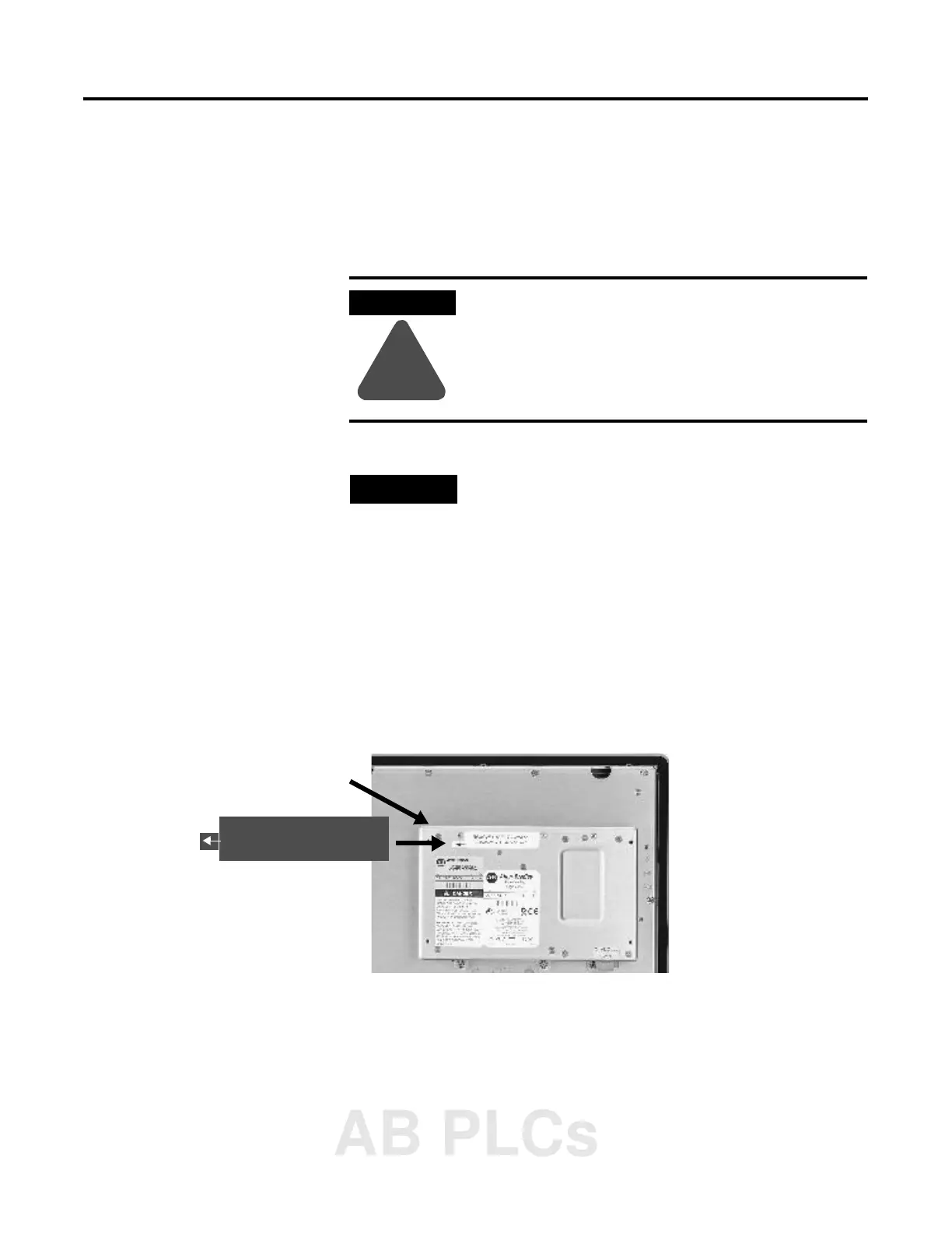
3. Remove the label covering the Communication Module
connector on the Logic Module.
WARNING
!
If you connect or disconnect any communication
cable with power applied to this module or any
device on the network, an electrical arc can occur.
This could cause an explosion in hazardous location
installations. Be sure that power is removed or the
area is nonhazardous before proceeding.
TIP
The Logic Module must be attached to the Display
Module before you attach the Communication
Module.
Logic Module
REMOVE LABEL TO INSTALL
COMMUNICATION MODULE
AB PLCs
 Loading...