EasyManuals Logo
Home>Allen-Bradley>Controller>PowerFlex 4M

Allen-Bradley PowerFlex 4M User Manual

Allen-Bradley PowerFlex 4M
118 pages
To Next Page IconTo Next Page
To Previous Page IconTo Previous Page
Page #101 background imageLoading...
Page #101 background image
PowerFlex 4M Adjustable Frequency Drive FRN 1.xx - 2.xx User Manual
Publication 22F-UM001D-EN-E
Appendix C
RS485 (DSI) Protocol
PowerFlex 4M drives support the RS485 (DSI) protocol to allow
efficient operation with Rockwell Automation peripherals. In addition,
some Modbus functions are supported to allow simple networking.
PowerFlex 4M drives can be multi-dropped on an RS485 network using
Modbus protocol in RTU mode.
For information regarding DeviceNet o
r other communication protocols,
refer to the appropriate user manual.
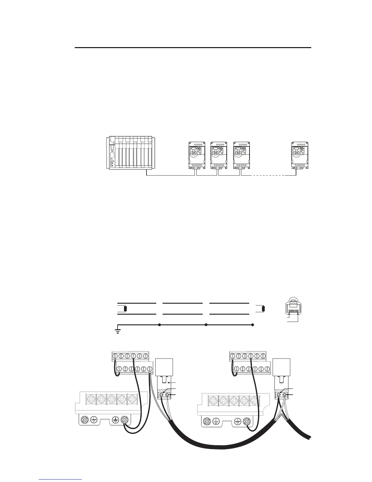
Network Wiring
Network wiring consists of a shielded 2-conductor cable that is
daisy-chained from node to node.
Figure C.1 Network Wiring Diagram
Controller
01 02 03 04 05
11 12 13 14 15
06
16
*
W/T3V/T2U/T1
DC+
DC-
Master
PowerFlex 4M
Node 1
4
5
PowerFlex 4M
Node 2
4
5
PowerFlex 4M
Node "n"
4
5
TxRxD+
TxRxD-
TxRxD+
TxRxD-
TxRxD+
TxRxD-
120 ohm resistor
120 ohm resistor
FRONT
PIN 8
PIN 1
NOTE: The shield should be grounded at ONLY ONE location.
TxRxD+
TxRxD-
RS485
(DSI)
AK-U0-RJ45-TB2P
RS485
(DSI)
TxRxD+
TxRxD-
*Terminal block for Frame A and B drives
is shown here.
01 02 03 04 05
11 12 13 14 15
06
16
Shield Shield Shield
*
W/T3V/T2U/T1
DC+
DC-

Table of Contents

Questions and Answers:

Question and Answer IconNeed help?

Do you have a question about the Allen-Bradley PowerFlex 4M and is the answer not in the manual?

Allen-Bradley PowerFlex 4M Specifications

General IconGeneral
BrandAllen-Bradley
ModelPowerFlex 4M
CategoryController
LanguageEnglish

Related product manuals