18 Rockwell Automation Publication 750COM-UM009A-EN-P - May 2017
Chapter 1 Getting Started
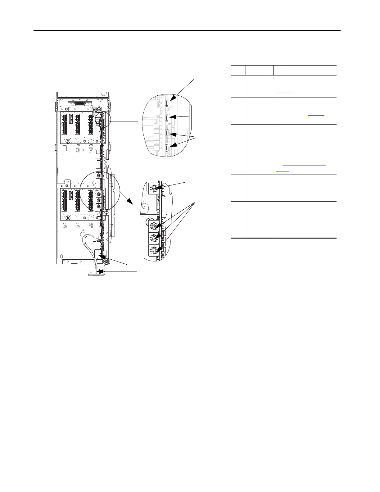
Components
Features
The features of the built-in EtherNet/IP interface include the following:
• Switches are used to set an IP address before power is applied to the
drive. Other methods are also available to configure the IP address:
– Interface parameters
– BOOTP (Bootstrap Protocol) server
– DHCP (Dynamic Host Configuration Protocol) server
• Configuration tool compatibility between the built-in EtherNet/IP
interface and host drive:
– PowerFlex 20-HIM-A6 or 20-HIM-C6S HIM (Human Interface
Module) on the drive, if installed
– Connected Components Workbench™ (CCW) software, release 10
or later
• Indicators that report the status of the built-in EtherNet/IP interface
and network communication. They are visible when the drive cover is
open or closed.
• Controller hierarchy that can be configured to transmit data to and
from a controller.
Item Part Description
1Status
Indicator -
ENET
Indicates the overall status of
network communication. See
Chapter 6, Troubleshooting.
2Status
indicators -
LNK1 and
LNK2
Indicates the status of the
network link to each of the two
physical ports. See Chapter 6,
Troubleshooting.
3 IP Address
Switches
Sets the IP address of the interface
(port 0) when not using any of
these other methods:
• Interface parameters
•BOOTP server
• DHCP server firmware
See Setting the IP Address on
page 26 for details.
4Ethernet
Connectors
RJ45 connectors for the Ethernet
cable. The connectors are CAT-5
compliant to deliver data over a
100 Base-TX Ethernet networks.
5 DPI™ Port 2
and 3
Cable connection for DPI port 2
handheld and remote options. DPI
port 3 is available by using a DPI
splitter part number 1203-S03.
6 Reserved
Drive Control Pod
Drive STS Indicator
Components that are shown have the
HIM bezel open and the drive cover
removed
1
3
4
5
2
6
Ones
Position
Hundreds
Position
Tens
Position

 Loading...


