Rockwell Automation Publication 1783-IN022A-EN-P - July 2023 12
Stratix 5200 Ethernet Managed Switches Installation Instructions
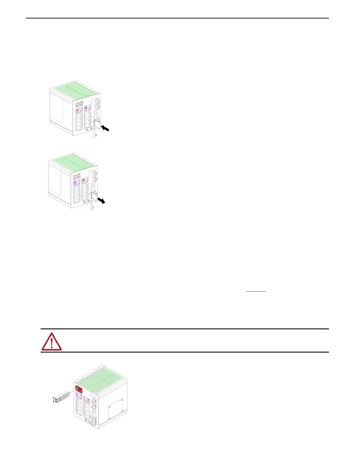
Install or Remove the SD Card
To install or replace the optional SD card, follow these steps.
1. On the front of the switch, locate the door that protects the SD card slot.
2. Loosen the captive thumbscrew at the top of the door by using a screwdriver to open the door.
Be careful when pulling out the SD Card guard cover so the retainer does not pop out of place.
3. To install the card, slide it into the slot, and press it firmly in place until it latches in the spring loaded mechanism.
The card is keyed so that you cannot fully insert it the wrong way.
4. To remove the card, push it in and let it pop out via the spring-loaded mechanism. Grasp the card top and pull it out. To protect it from static discharge, place it in an anti-
static bag.
5. Close the guard door and fasten the captive screw by using a screwdriver to keep the door in place.
Install or Remove an SFP Module
SFP modules are inserted into SFP module slots on the front of the switch. These field-replaceable modules provide the uplink optical interfaces, send (TX) and receive (RX).
You can use any combination of compatible SFP modules:
• Each SFP module must be of the same type as the SFP module on the other end of the cable. The cable must not exceed the stipulated cable length for reliable
communications.
• Once you install SFP modules in the switch, the overall temperature rating of the combined modules (switch and SFP modules) is limited to the lowest maximum
temperature rating and the highest minimum temperature rating.
• For cable length and temperature specifications, see the Stratix Ethernet Device Specifications Technical Data, publication 1783-TD001
.
To insert or remove an SFP module into an SFP slot, follow these steps.
1. Attach an ESD-preventive wriststrap to your wrist and to a grounded bare metal surface.
2. To install and SFP module, do the following.
a. Grasp both sides of the SFP module and align the module sideways in front of the slot opening.
b. Insert the SFP module into the slot as shown in the following figure until you feel the connector on the module snap into place in the rear of the slot.
ATTENTION: If the SFP module cannot be fully inserted, stop! Do not force the module into the slot. Rotate the SFP module 180° and try again.
 Loading...


