Modero G5 Touch Panels - Installation & Hardware Reference Manual
30
| TOC
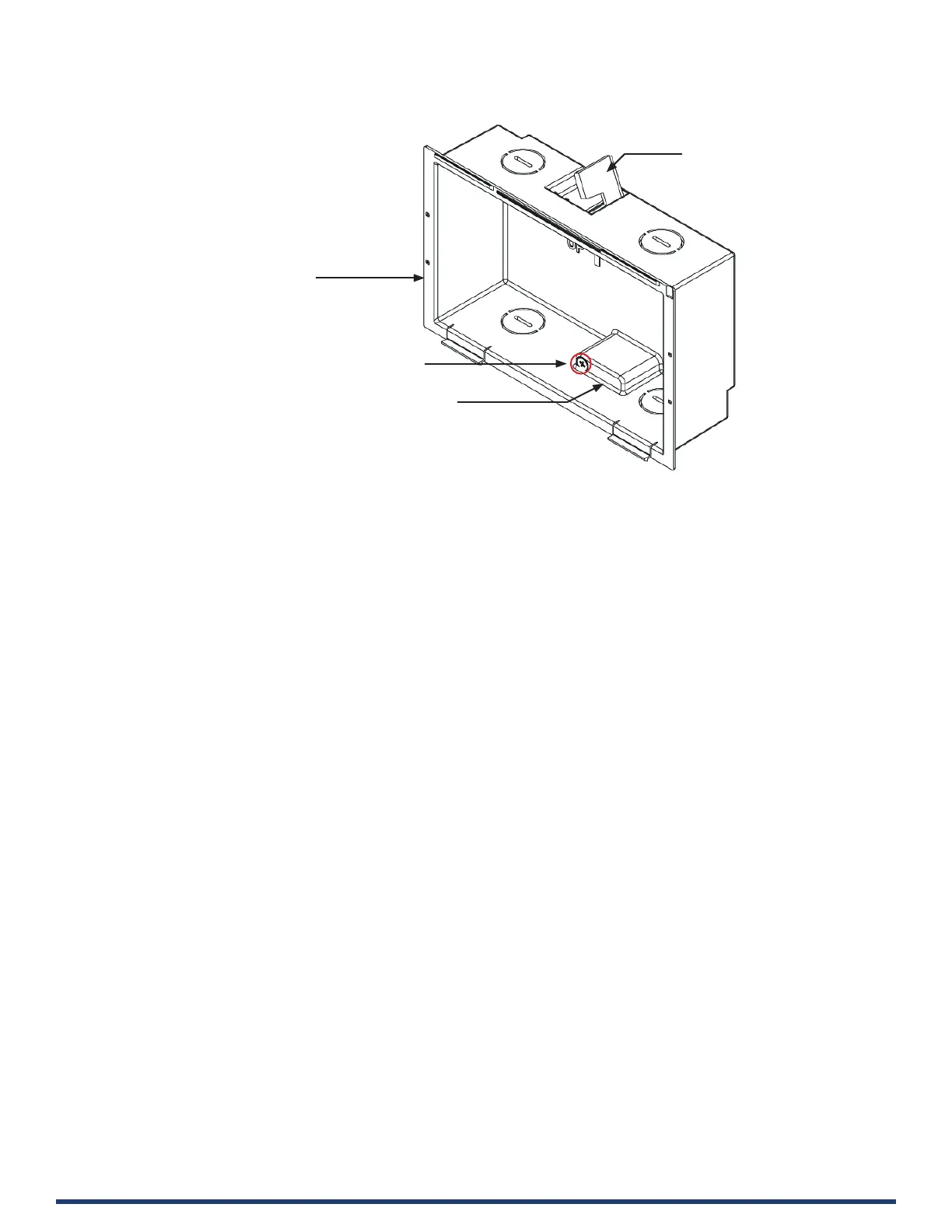
FIG. 26 MD-702 Backbox - Locking tab and locking tab screws (X2)
CAUTION: The maximum recommended torque to screw in the locking tabs on the plastic Backbox is 5 IN-LB [56 N-CM].
Excessive torque on the tab screws can strip out the locking tabs or damage the Backbox.
• Extend the Locking Tabs only AFTER the Backbox is inserted into the wall.
• When installing the Backbox, make sure that it is positioned correctly.
• The Backbox is clear to allow visual conrmation that the tabs have been extended and are gripping the wall, as well as in
assisting with removal if necessary.
STEP 2: Insert Connectors on the Touch Panel
1. Before installing the touch panel into the Backbox, connect the Ethernet and USB cables to the rear of the panel.
2. Remove power at the terminal end before continuing with the installation.
NOTE: Do not disconnect the connectors from the touch panel. The panel must be installed with the connectors attached be-
fore being inserted into the mounting surface.
Locking Tab (X2)
Locking Tab (X2)
7” Wall Mount Backbox
Locking Tab screw (x2) - tighten to extend
both of the Locking Tabs
(max torque = 5 IN-LB)

 Loading...