Installation Procedure
Autopulse-442R 50098:F 05/24/2001 13
Section 2 Installation Procedure
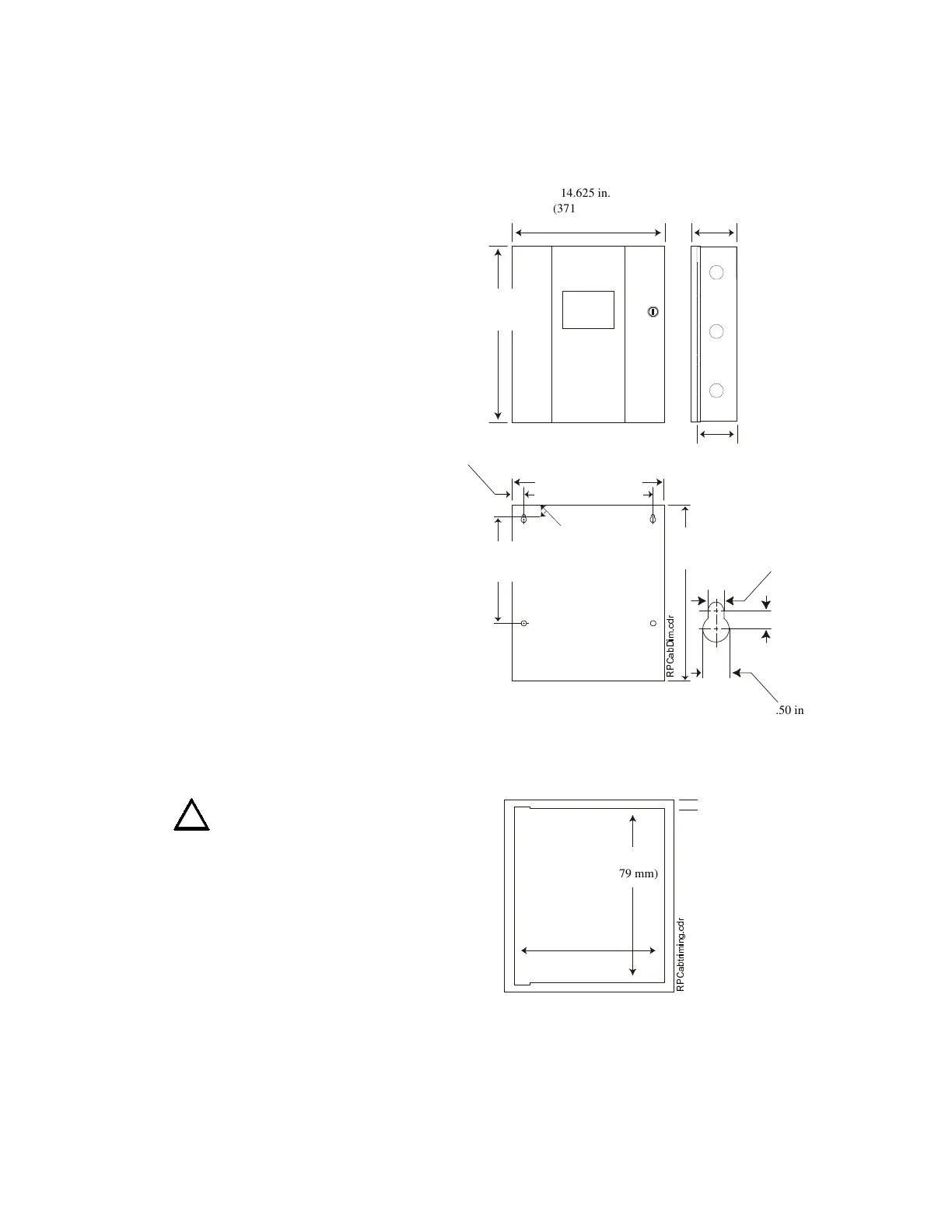
&DELQHW0RXQWLQJ
Carefully unpack the system and
check for shipping damage. The
printed circuit board should be
removed to prevent damage;
set it aside carefully before
mounting cabinet and pulling
conduit.
The entire unit is housed in a
standard sheet-metal enclosure
with 1/2 in. (12.7 mm) and
3/4 in. (19.05 mm) conduit
knockouts available on the top
and bottom. Select knockouts
according to the number of
conduits required by “UL Power-
limited Wiring Requirements” in
Section 2.2.
Select a suitable location in a
clean, dry, vibration-free
environment that is not subject to
extreme temperatures. Locate the
top of the cabinet approximately
five feet above the floor with the
hinge on the left. The panel must
be easily accessible for mainte-
nance; the hinged door requires a
minimum clearance of 14 in.
(355.6 mm) to open. Securely
mount the cabinet using the
mounting holes provided. Attach
the trim ring.
WARNING: Do not apply
power to this control unit until
printed circuit board has been
reinstalled, and all connections
have been made and verified.
53&DEWULPLQJFGU
14.625 in.
(371.48 mm)
14.625 in.
(371.475 mm)
TR-4XR Trim Ring
(Red Steel, 16 Gauge)
5.375 in.
(136.53 mm)
1.5 in (38.1 mm)
14.5 in. (368.3 mm)
12.5 in. (317.5 mm)
4.750 in.
(120.65 mm)
16.125 in.
(409.58 mm)
16 in.
(406.4 mm)
9.5 in.
(241.3 mm)
1 in.
(25.4 mm)
.312 in (7.93 mm)
53&DE'LPFGU
16.125 in.
(408.79 mm)
.50 in.
(12.70 mm)
.5 in (12.7 mm)
 Loading...