- 19 -
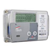
Version 1: M-BUS + 4 pulse IN
M
M-BUS
M
M
M
IN4
IN3
IN2
IN4
1
2
3
4
5
6
8
97
10
M
M
IN2
IN1 M-BUS
1
2
4
53
6
7
8
9
10
M
M
M
M
IN4
IN3
IN2
IN1
NC
NC
1
2
3
4
5
6
87
9
10
M
M
M
IN3
IN2
IN1
NC
NC
1
2
3
4
5
6
7
8
10 9
M-Bus
Master
Version 3: 4 pulse IN
Version 2: M-BUS + 2 pulse IN + 1 pulse OUT
Version 4: 3 pulse IN + 1 pulse OUT
Vcc
GDN
OUT
Vcc
GND
OUT
M-Bus
Slave
M-Bus
Master
where:
IN1, IN2, IN3, IN4 are the pulse input terminals;
M are the pulse input terminals connected to the interface common;
M-BUS is the I/O for connection with the M-Bus line (any wiring connection sequence is allowed);
NPN transistor symbol is the pulse output;
NC is spare, i.e. not used in the given module version.
7.1.2. Interface technical parameters
The table below shows the technical parameters of individual interface blocks
Interface parameters
Enclosure
Integrated with the heat meter main enclosur
by 2 snap fasteners; electrical connection:
2x5 pin (2.54 mm matrix)
Operating temperature ºC 0 ÷ +55
Power supply
M-Bus interfaces are powered
by the transmission lines
M-BUS - optional
Maximum voltage V 42
Maximum interface current consumption mA 2
Wire insulation voltage rating V > 500
Maximum wire length in network m < 1000*
Maximum no. of interfaces in network depending on the permissible converter load
Baud rate Baud 300, 600, 1200, 2400, 4800, 9600
Maximum cross section of supply wires mm² < 1,5
Recommended M-Bus cable YnTKSY 1x2x1,0 mm
Maximum recommended readout frequ-
ency (at 2400 bauds)
s 900
Internal interface register refresh interval s
60 (the register refresh interval is the time
at which M-Bus polls the heat meter for the
actual register status)
 Loading...