- 4 -
1. SUBJECT
This description is intended to present the characteristics, parameters and operation of Elf compact heat
meters manufactured by Apator-Powogaz. The heat meters are intended to meter the heat consumption
taken from heat distribution networks by small loads (e.g. apartments) with the heat power rating of
0.3kW to 850 kW with Building Code compliant treated water as the heating medium. The heat meters are
manufactured in five sizes for four nominal volume flow sizes. The sizes differ in diameter and connection
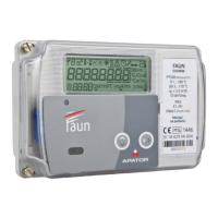
types. The heat meter consists of a flow transducer, a pair of Pt 500 temperature sensors with wells and
an electronic indicator resolver. All components form an integrated set for the user, i.e. the complete
heat meter. The installed sensors are type TOPE42 Pt 500 temperature sensors and butterfly flowmeters
without magnetic coupling which must be operated with only one specific type of electronic resolver.
Elf heat meters are compatible with remote reading interfaces and with up to four additional devices (e.g.
a water meter or a gas meter) equipped with pulsers. The interfaces available are: one Wireless M-Bus,
one M-Bus interface which enables connecting 2 additional pulsers and features a pulse output, an M-Bus
for connecting 4 additional pulsers, and one M-Bus with 4 additional pulser inputs or 3 pulser inputs and
one pulse output.
2. REGULATORY AND STANDARD COMPLIANCE
• Directive 2004/22/EC of the European Parliament and of the Council dated 31 March 2004 on measu-
ring instruments, with specific consideration to Annex MI-004, Heat Meters.
• PN-EN-1434 – Heat meters, 6 parts.
• PN-EN 61000 – Electromagnetic compatibility (EMC). Parts 2-4.
• PN-EN 13757 – Communication systems for meters and remote reading of meters. Parts 1-4
3. DESIGN, FUNCTIONAL DESCRIPTION & BASIC CHARACTERISTICS
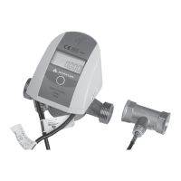
Elf compact heat meters consist of an electronic resolver with a pair of Pt 500 sensors permanently
integrated with a butterfly flowmeter. The electronic system is located in a small tamper-proof enclo-
sure which prevents access to electronic components and sensors after factory assembly. The base
of the electronic system enclosure is connected to the flowmeter body with a band clip locked with a
wire seal. The enclosure base is fastened to the rest of the enclosure with two screws; the enclosure
is sealed by applying a self adhesive seal made of a special brittle sheet at the enclosure separation
line, and on the fastening screw head opening. The electronic circuit features special pins for a jumper.
The removal of the jumper disables access to calibration and configuration of metrological parameters
of the heat meter. The part of the setup parameters which do not affect the measurement accuracy is
adjustable by the user, i.e. the administrator or the technical service.
The flowmeter rotor features a disk made of an EM-immune metal. The rotor revolutions are measured
by the electronic system with induction coils; only connecting the flowmeter to the electronic circuit
makes the flow transducer complete; addition of the temperature sensor pair completes the compact
flowmeter. The modern revolution detection method combines excellent metrological performance
with resistance to strong magnetic fields. The flow transducer system resolution enables detection of as
little as ¼ of rotor revolution; moreover, the implemented electronic calibration results in a very smooth
error chart within the entire range of flow variations.
The temperature sensors are permanently soldered to the resolver PCB. The temperature is measured
in 16-second intervals in the basic operating mode when flow is present. If there is no flow present, the
temperature is measured twice in the averaging period (cycle 1 duration). The heat gain is calculated
and added to the total consumption register at an interval of at least 8 seconds only if volume gain
occurs in the given period.
 Loading...