- 8 -
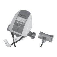
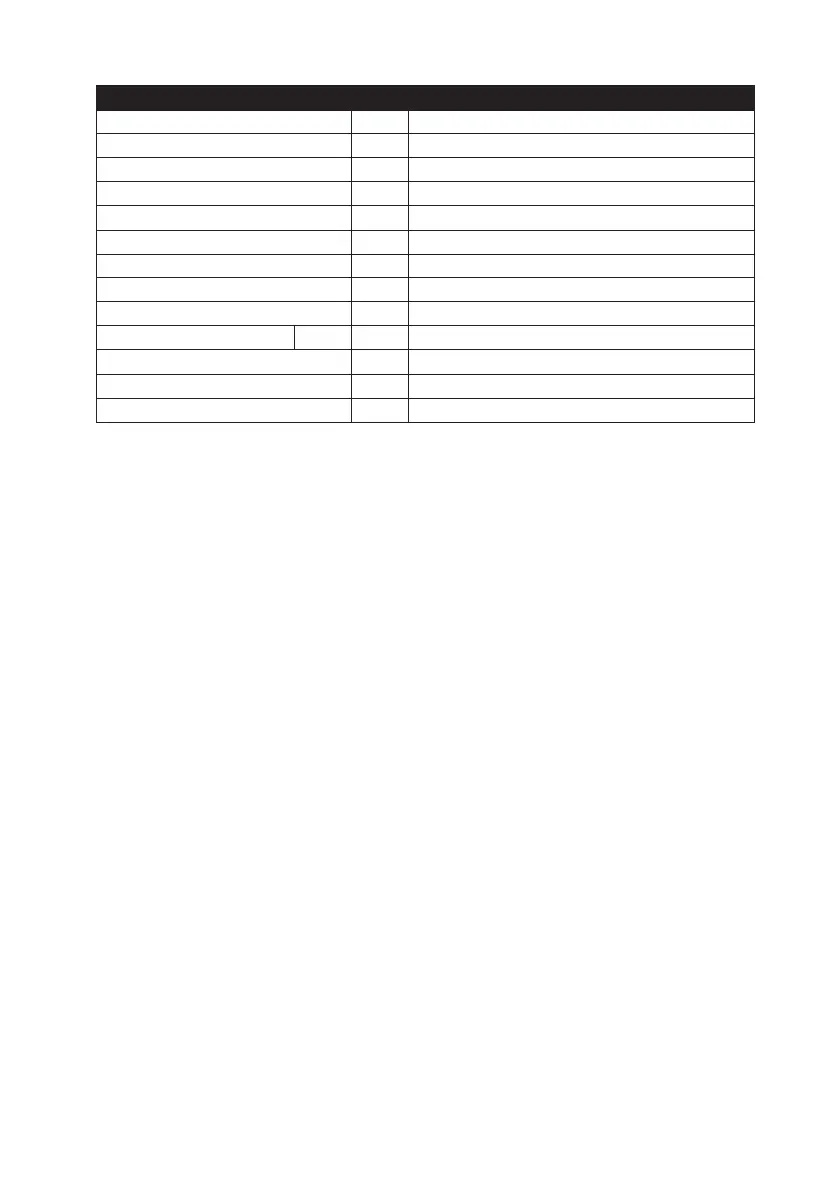
Temperature sensor pair
Manufacturer mark – APATOR POWOGAZ S.A.
Thermometer resistor – Pt 500 (TOPE42)
Method of connection with the resolver – soldered
Temperature measurement range °C
Θ
min
= 0 °C Θ
max
= 105 °C
Differential temperature range °C
Θ
min
= 3 °C Θ
max
= 104 °C
Maximum operating pressure MPa 1,6
Maximum measurement current mA 5
Sensor well material – steel, 1H18N9
Outer well material – No outer well
Limit MPE
E
t
%
E
t
= ±(0,5 + 3 * ΔΘ
min
/ ΔΘ)
Connection cable – spiral, PU insulation, 2x0.25 mm2, length: 2m
Overall dimensions mm 70 x 75 x 80
Weight kg 0,35
5. DATA TYPES
The measured and calculated data can be divided into two groups:
• actual data, which is determined in 8 second intervals (except for temperature values in the basic
operating mode);
• averaging period data (period adjustable by the user), displayed in the service data group;
• archive data, in up to 4 user-configurable cycles;
• configuration (service) data, which can also be adjusted by the user if not metrology-specific;
• test data, displayed in the test mode.
The data reading methods are described in the section of the heat meter operating guide. The following
presents the meaning and interpretation of measured values
5.1. Actual data
This is the data from the measurements and from the calculations made with the input of current me-
asurements. The data is updated every 8 seconds (except for the temperature data which is updated
every 16 seconds and only if the flow is present) and displayed as basic data; the exception is the real
time clock and the metrological test which are service data, despite the same update interval.
5.1.1. Heat consumption
Heat consumption is calculated as shown in Section 3, in one of three selectable energy units, e.g. GJ,
kWh or Gcal (the unit symbol is not displayed). The user must select the unit upon ordering, since it
is not possible to change it once the heat meter has been sealed. The heat consumption register is 11
decimal digits long, with the least important four digits displayed in the test data group.
5.1.2. Water volume
Water volume is calculated by totalling very small volume doses per one revolution of the flow trans-
ducer rotor. The revolution measurement resolution is ¼ of revolution, yet this resolution is only used
in the sense of rotation detection. Volume is summed only if a full revolution in the proper sense of
rotation is detected. The revolution value in millilitres varies with the instantaneous rotational speed
which in turn is determined by measuring the time interval between two successive revolutions. The
calibration of the flow transducer consists in experimental determination of the revolution value at
 Loading...