- 22 -
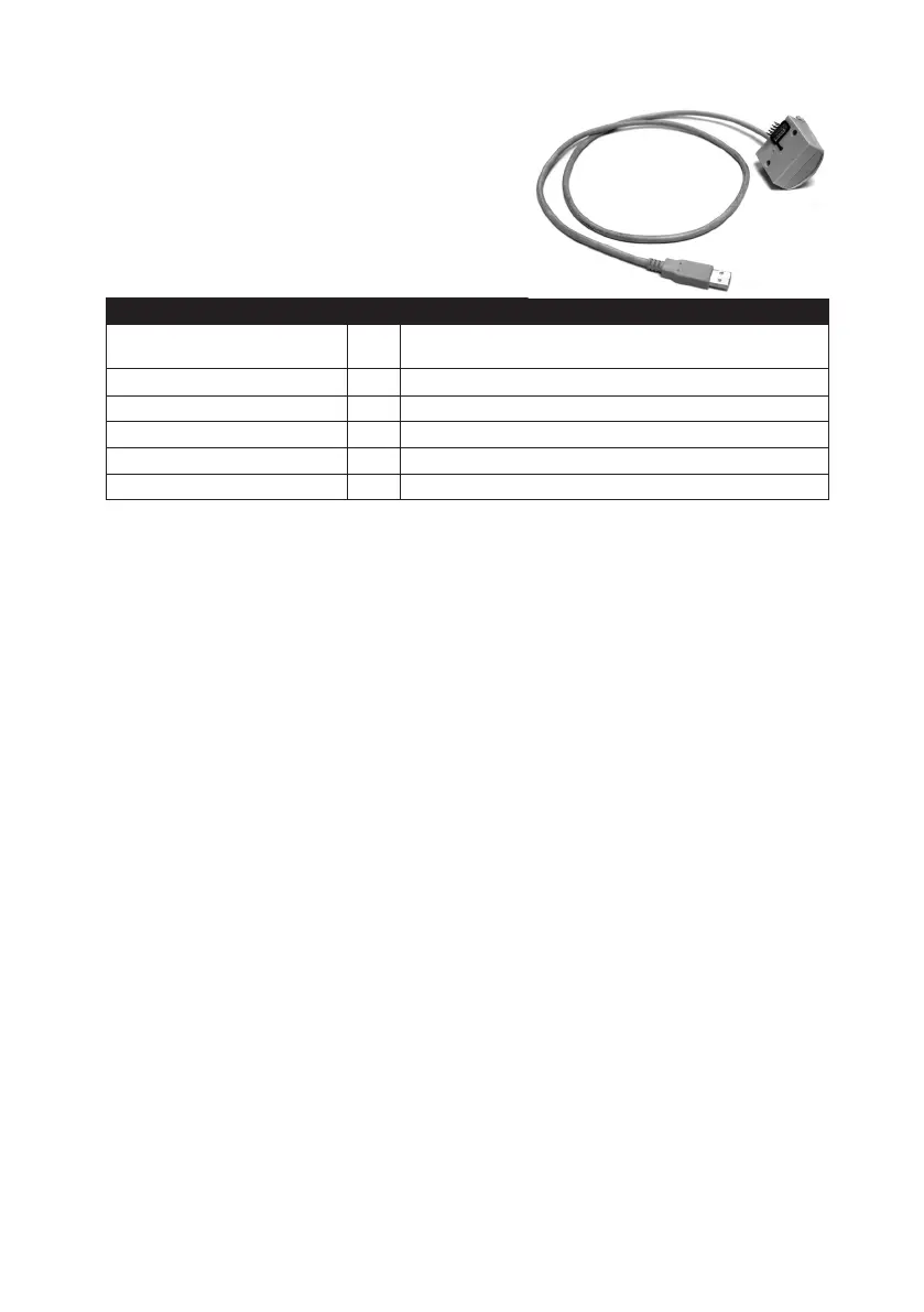
7.3. USB interface
The USB communication interface enables quick and
easy readouts of data from the meter, and to configu-
re the available parameters. The main advantage here
is that the interface requires no additional transmis-
sion converters. See the separate operating manual
for the instructions for driver installation and commu-
nication software setup.
USB module
Enclosure
Integrated with the heat meter main enclosure by 2 snap
fasteners; electrical connection: 2x5 pin (2.54 mm matrix)
Operating temperature range ºC
0 ÷ +55
Power supply 5V DC, directly from the USB interface port of the reader
Data transmission speed b/s 300 to 9600
Communication connector type - USB, A
USB cable length m 1,5
8. SHIPPING AND MOUNTING
Transport the heat meters only on fully enclosed vehicles and with protection against shifting and da-
mage. Store the heat meters in unit packaging in dry, clean indoor areas above +5 °C and below 90%
of relative humidity. The heat meter can be identified (traced) by the markings and technical data loca-
ted on the enclosure label. The shipment addressee should inspect the condition of the parcel before
unpacking the heat meter, especially:
• the condition of the packaging;
• completeness of the shipment;
• the types and versions against the order;
• the condition of the enclosure and its seals (see section 8.1).
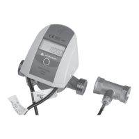
The heat meters are delivered only as complete units with the sensor pair installed, where one sensor
is installed in the flow transducer body and the other is installed in a suitable fitting (i.e. a tee joint or a
valve) connected to the heat pipe.
The quick user manual must be enclosed with the product.
Check the heat meter for mechanical damage before installation. If any damage, missing parts or discre-
pancies against the specifications is found, send a claim for the affected unit.
The product must be installed in the heating system piping by a professional service and according to
the design requirements of the building and of PN-EN 1434-6:2007.
Note the following:
1. The flow direction shown by the arrow on the flow transducer body must match the actual flow in
the metering circuit.
2. The heat meter must be installed in the correct pipe (supply or return), as indicated on the sticker on
the body.
a. If the heat meter is installed in the supply circuit, install the supply temperature sensor in the flow
transducer body and the return sensor in the return line.
b. If the heat meter is in the return circuit, install the supply temperature sensor in the supply line
and the return sensor in the flow transducer body.
 Loading...