FOR MODELS: JGW, JGR AND JGJ SECTION 4 - LUBRICATION AND VENTING
1/01 PAGE 4 - 15
DNFT. Retain for partial credit return. Disassemble the magnetic housing from the switch
body by loosening the (2) 1/4”-20 set screws on a new DNFT. Be sure magnet pin and
spring are intact and working in the magnetic housing assembly. You should feel spring
force when pushing on the magnet pin by hand. Screw the magnetic housing assembly into
the end of the divider valve housing. Be sure set screws are loosened and slide the switch
body all the way onto the nut of the magnetic assembly. Tighten set screws and re-attach
wiring and conduit.
Assembly Instructions For Divider Valves
NOTE: THE CENTER TIE ROD IN THE BASEPLATE IS OFFSET SO THAT THE INTER-
MEDIATE BLOCKS CANNOT BE ASSEMBLED BACKWARDS. IF EXCESSIVE
FORCE IS ENCOUNTERED DURING ASSEMBLY, MAKE SURE BLOCK IS NOT
BACKWARDS.
1. Screw three tie rods into inlet block until ends are flush with surface of block.
2. Slide inlet gasket onto tie rods.
3. Alternately slide an intermediate block and an intermediate gasket plate onto the
tie rods until the last intermediate block is in place.
4. Discard remaining intermediate gasket plate.
5. Slide end gasket plate and end block onto tie rods.
6. Lay baseplate assembly on flat surface and tightening nuts to 72 lb-in. (8.1
N·m), torque.
7. Mount divider valves with gasket plates onto baseplate and tightening mounting
screws to 108 lb-in. (12.2 N·m), torque.
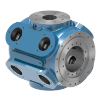
Operation
The inlet passageway is connected to all piston chambers at all times with only one piston
free to move at any one time. With all pistons at the far right, lubricant from the inlet flows
against the right end of piston 1. (See Figure 4-5: illustration 1)
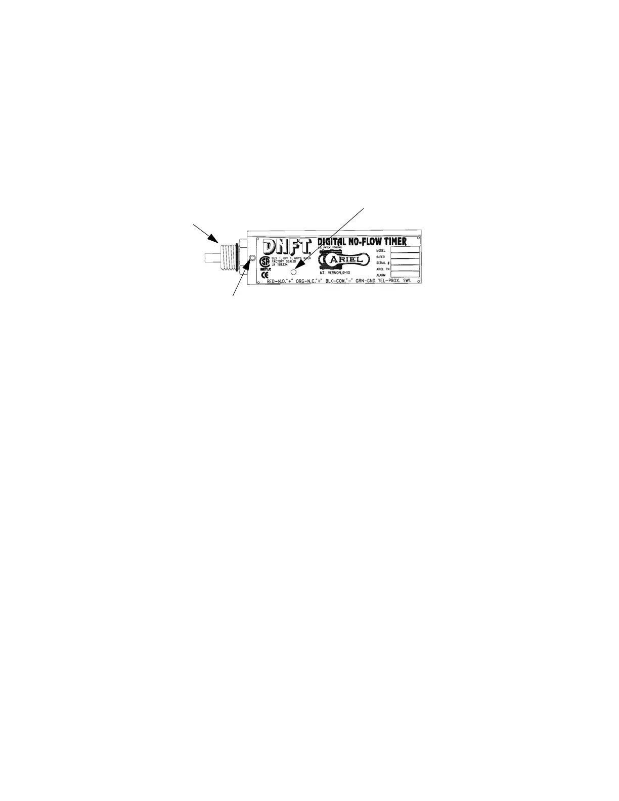
FIGURE 4-4: DIGITAL NO-FLOW TIMER SWITCH - (DNFT)
(2) 1/4” x 20
Set Screws
Amber LED Cycle
Indicator
Magnetic Housing
Assembly
Red-Normally Open; Orange-Normally Closed; Black-
Common; Green-Ground; Yellow Proximity Switch
 Loading...