FOR MODELS: JGW, JGR AND JGJ SECTION 4 - LUBRICATION AND VENTING
PAGE 4 - 16 1/01
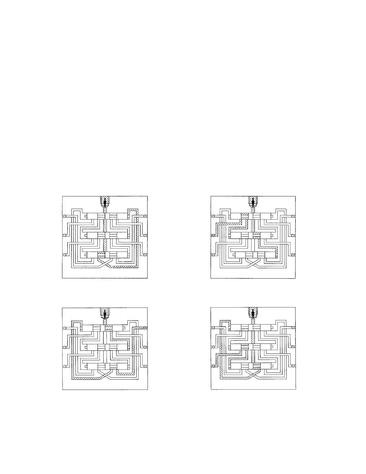
Lubricant flow shifts piston 1 from right to left dispensing piston lube through connecting
passages to outlet 1. Piston 1 shift directs flow against right side of piston 2. (See Figure 4-
5: illustration 2)
Lubricant flow shifts piston 2 from right to left dispensing lube through valve ports of piston 1
and through outlet 2. Piston 2 shift directs lubricant flow against right side of piston 3. (See
Figure 4-5: illustration 3)
Lubricant flow shifts piston 3 from right to left dispensing lube through valve ports of piston 2
and through outlet 3. Piston 3 shift directs lubricant through connecting passage to the left
side of piston 1. (See Figure 4-5: illustration 4)
Lubricant flow against left side of piston 1 begins the second half-cycle which shifts pistons
from left to right dispensing lubricant through outlets 4, 5 and 6 of the divider valve.
If pistons refuse to move, check for air lock in one or more valve ports by manually shifting a
piston from right to left.
FIGURE 4-5: DIVIDER VALVE OPERATION SCHEMATIC
Inlet Inlet
Illustration 1 Illustration 3
InletInlet
Illustration 2 Illustration 4
Outlet
1
Outlet
5
Outlet
6
Outlet
4
Outlet
2
Outlet
3
Outlet
1
Outlet
5
Outlet
6
Outlet
1
Outlet
5
Outlet
6
Outlet
1
Outlet
5
Outlet
6
Outlet
4
Outlet
2
Outlet
3
Outlet
4
Outlet
2
Outlet
3
Outlet
4
Outlet
2
Outlet
3
 Loading...