ON
OFF
1
2
5
6
l
FR
Dans le cas d’une dureté de l ’eau
supérieure à 20 °f, prévoir un traitement de
’eau.
NL
Bij waterhardheid van meer dan 20
°f, een water verzachter voorzien.
DE
Wenn
der Härtegrad des Wasser über 11°dH (20 °f)
beträgt, ist eine Wasserenthärtung
vorzusehe
n.
IT
Se l’acqua ha una durezza
superiore a 20 °f, prevedere un dispositivo di
trattamento.
ES
En el caso de que la dureza
del agua sea superior a 20 °f, prever un
tratamiento del agua.
PT
Nos casos em que a
dureza da água seja superior a 20 °f, prever
um sistema de tratamento de água.
UK
If the
water hardness is more than 20 °f, install a
water softener.
CZ
V prípade, ze tvrdost vody
presahuje 20 °f, je treba aplikovat vhodnou
úpravnu vody.
HU
Ha a víz keménysége
nagyobb, mint 20°f német keménységi fok,
akkor a víz kezelésér l gondoskodni
kell.
PL
twar
wody jest w
nale
y zainstal
ow
owiednie ur
zenie.
20 °f su sertli
ini geçen sular için su
ıtma tavsiye edilmelidir (su arıtma
teriye aittir).
RO
Daca apa are o duritate
are dacat 20 °f, este necesara tratarea in
l a acesteia.
RU
.
XXXX
xxxxx
xxxxx
xxx
XXXX
xxx
MIN
Q
G30 - G31 28/37 mbar
1009942-05
5
4
2
1
3
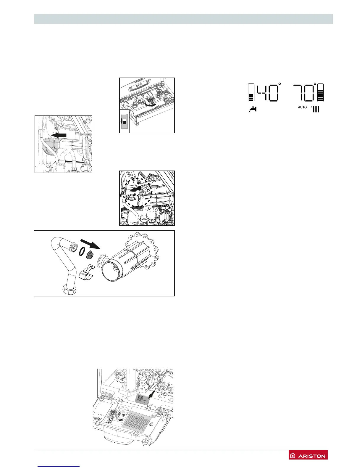
Converting the appliance from Natural gas to LPG
These appliances are designed to operate with different gas
types.
The appliance must only be converted for use with a different
gas type by a Gas Safe Registered installer.
To convert the appliance to LPG:
(use these instructions in conjunction with the Instruction sheet
supplied with the LPG Kit).
1.
Electrically isolate the appliance (g 1)
2. Turn off the gas supply (g 2)
3. Remove the outer case, lower the
front control panel.
4. Remove the silencer (g 3)
5. Disconnect the gas supply from
the venturi assembly (g 4)
6. Inset the correct diaphragm
(depending on the output of the
appliance) into the venturi spigot
(g 5)
7. Reassemble the gas supply onto the venture assembly (g 4)
and reattach the silencer.
8. Turn on gas supply and test for tightness
9. Purge gas supply
10. Turn the electrical supply on to the appliance.
11. Commission the appliance, check the working pressure is
adequate then test and adjust the CO² values at maximum
and minimum output described in the commissioning section
of the appliance installation instructions. Ensure the ue
gas analyser used is calibrated and set for the gas group
the appliance is being
adjusted for.
12. Check the appliance
for gas leaks using
gas leak detection
uid.
13. Afx the label to
the appliance that
is supplied with the
conversion kit.
AUTO function
This is a function which enables the boiler to automatically
adapt its operation routine (the temperature of the heating
elements) in line with the outdoor conditions, in order to achieve
and maintain the requested room temperature conditions.
Depending on the peripheral units connected and the number
of zones controlled, the boiler adjusts its ow temperature
automatically.
The various
corresponding
parameters should
therefore be set (see
adjustments menu).
To activate the function,
press the
button.
Example 1:
Single zone system (high-temperature) with on/off room
Thermostat:
In this case the following parameters must be set:
4 21 - Activation of temperature adjustment using sensors
- Select 1 = Basic temperature adjustment
2 44 - Boost Time (optional)
The wait time for the ow temperature increase in steps of
4°C may be set. The value varies according to the type of
system and installation.
If the Boost Time value = 00 the function is not activated.
Example 2:
Single zone system (high-temperature) with on/off room
Thermostat + outdoor sensor:
In this case the following parameters must be set:
4 21 - Activation of temperature adjustment using sensors
- Select 3 = outdoor sensor only
4 22 - Temperature adjustment curve selection
- Select the relevant curve according to the type of
system, installation, heat insulation used in the building,
etc.
4 23 - Perform a parallel curve shift if necessary, increasing
or decreasing the set-point temperature (this may also
be modied by the user, using the heating temperature
adjustment knob, which, with the Auto function activated,
is used to shift the curve in a parallel manner).
Example 3:
Single zone system (high-temperature) with Sensys controller +
outdoor sensor
In this case the following parameters must be set:
4 21 - Activation of temperature adjustment using sensors
- select 4 = outdoor sensor + room sensor
4 22 - Temperature adjustment curve selection
- Select the relevant curve according to the type of
system, installation, heat insulation used in the building,
etc
4 23 - Perform a parallel curve shift if necessary, increasing or
decreasing the set-point temperature. (This may also be
changed by the user by the buttons 8 which, with the
Auto function activated, is used to shift the curve in a
parallel manner.)
4 24 - Inuence of room sensor
- used to adjust the inuence the room temperature has
on the calculation of the set-point ow temperature (20 =
maximum, 0 = minimum).
Note: See page 40 for details on accessing menus.
 Loading...