8 ATS4000 Installation and Quick Programming Guide
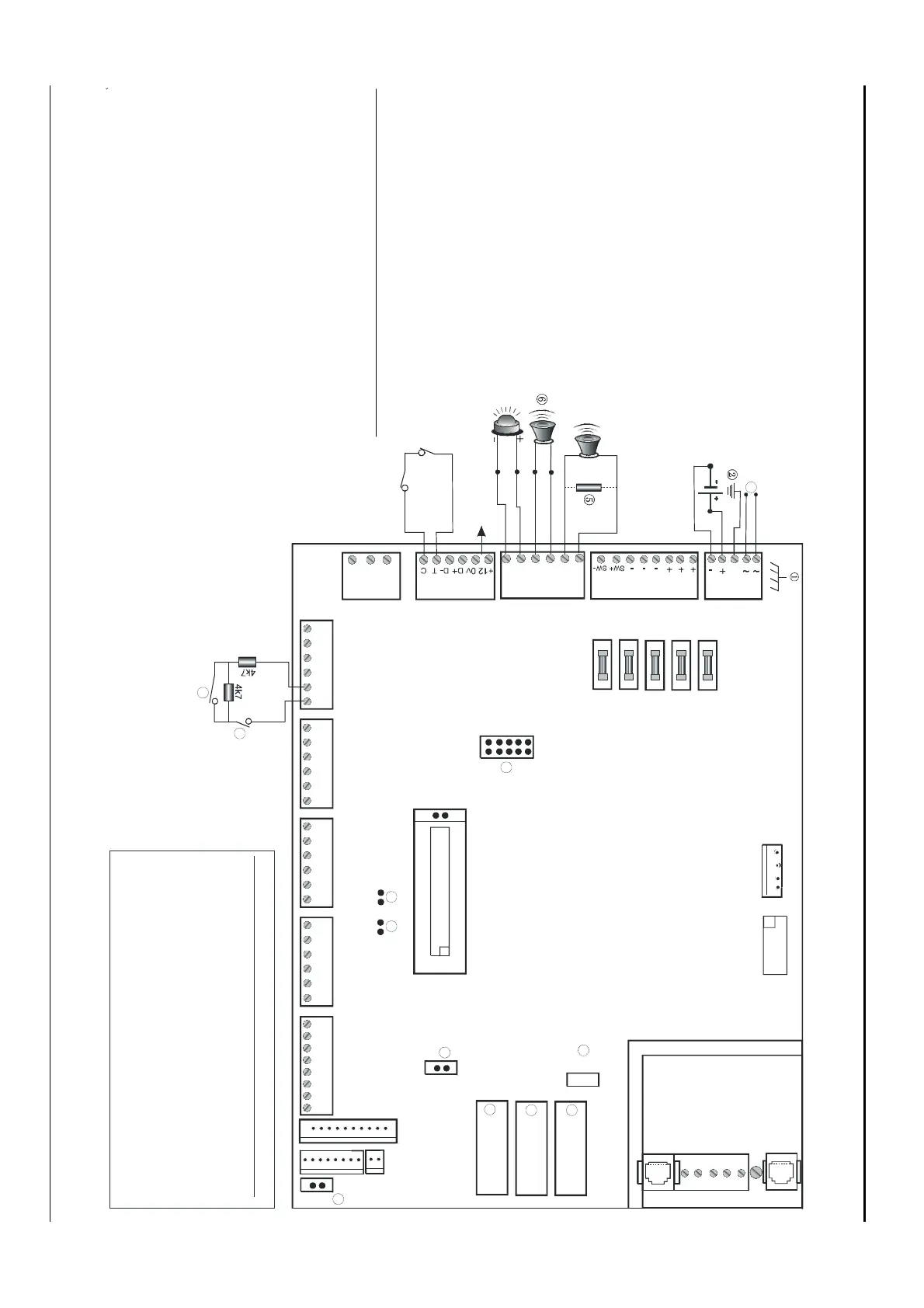
4. Connection diagrams
(1) Earth Lug
(2) System earth (see details page 4)
(3) 12 V battery
(4) External 8 Ohm siren speaker or sirene
(5) 1K resistor must be fitted if external siren
not connected
(6) Internal 8 Ohm siren speaker
(7) 12 V strobe
(8) System databus
(9) Normally closed front panel tamper contact
(10) Normally closed rear panel tamper contact
(11) Normally Closed Alarm Contact
(12) Normally Closed Tamper contact
(13) +12V Output board
(14) EPROM (factory fitted)
(15) Flash
(16) RAM or IUM (optional)
(17) ISP Circuit programming connector,
used to program the CPLD (factory used)
(18) Test 1 – Use for resetting the Master Engineer code
(19) Test 2 – Factory use only
(20) To be used for ATS1202 (only with ATS3000)
(21) Kill - Factory default control panel when shorted
(22) Transformer AC connection
J2 - J6 Zone wiring
J7 ATS1202 Zone expansion
J8 CLKOUT (ATS1810/1820)
J9 Bell
J10 Comms and panel tamper wiring
J11 Computer/printer expansion
J13 Sirens/Strobe Connection
J14 Auxiliary power
J17 Power
J18 Serial connection (RS232)
J20 ISDN/Audio Interface
J15 RJ45 PTT connector (not fitted)
J16 PSTN Line connection
J19 RJ45 PTT connector
E
r
h L
17 - P
w
r
m
r
h
il
4
12 V
r
.
14 -
xili
r
w
r
1
ir
n
r
nn
i
nEx
rn
l
hm
ir
n
k
r
r
ir
n
1K resistor must be fitted if external siren not connected.Internal 8 Ohm siren speaker 12 V strobeJ3 - Comms and panel tamper wiring System databusNormall y closed front panel tamper contact
Normally closed rear panel tamper contactJ9 - BellJ2 to J6 Zone wiringNormall y Closed Alarm ContactNormally Closed Tamper contactJ7 ATS1202 Zone expansion J8 - CLKOUT (ATS1810/1820)
+12V Output boardJ11 Computer/printer expansion J18 Serial connection (RS232)J20 ISDN/Audio Interface J15/J19 RJ45 PTT connector (not fitted)J16 PSTN Line connection EPROM (factory fitted)
Flash/RAM or IUM (optional)ISP. Circuit programming connector, used to program the CPLD (factory used)Test 1 Use for resetting the Master Engineer code.Test 2 Factory use onlyTo be used for ATS1202 (only with ATS3000)
J61 C 2 C 3 C
④
①
③
S+S-S+S-+-
⑦
➉
➈
1211
1
TH1TH3TH5TH2TH4
NEGCPOS
4
47
1
11
12
21
14
1
1
J11
ABAXBXEA
1
2
TST1T
T2
+12V
-1
I
P
KILL
12V RX TX
V
1413
15
J9
161
1
1
1
17171
1
2
24
272
29
1
2
4
28
17
14
1
T
m
r
r
rvi
nn
i
n -
ri
P
ATS3000/4000J18DB12VRX.............................TX2TX.............................RX30V..............................GND7
1011121314
151617181920
21222324252627
282930313233
34
2
4
71
89
22
Kill - Factory default control panel when shorted
Transformer AC connection
E
r
h L
17 - P
w
r
m
r
h
il
4
12 V
r
.
14 -
xili
r
w
r
1
ir
n
r
nn
i
nEx
rn
l
hm
ir
n
k
r
r
ir
n
1K resistor must be fitted if external siren not connected.Internal 8 Ohm siren speaker 12 V strobeJ3 - Comms and panel tamper wiring System databusNormally closed front panel tamper contact
Normally closed rear panel tamper contactJ9 - BellJ2 to J6 Zone wiringNormall y Closed Alarm ContactNormally Closed Tamper contactJ7 ATS1202 Zone expansion J8 - CLKOUT (ATS1810/1820)
+12V Output boardJ11 Computer/printer expansion J18 Serial connection (RS232)J20 ISDN/Audio Interface J15/J19 RJ45 PTT connector (not fitted)J16 PSTN Line connection EPROM (factory fitted)
Flash/RAM or IUM (optional)ISP. Circuit programming connector, used to program the CPLD (factory used)Test 1 Use for resetting the Master Engineer code.Test 2 Factory use onlyTo be used for ATS1202 (only with ATS3000)
J61 C 2 C 3 C
④
①
③
S+S-S+S-+-
⑦
➉
➈
1211
1
TH1TH3TH5TH2TH4
NEGCPOS
4
47
1
11
12
21
14
1
1
J11
ABAXBXEA
1
2
TST1T
T2
+12V
-1
I
P
KILL
12V RX TX
V
1413
15
J9
161
1
1
1
17171
1
2
24
272
29
1
2
4
28
17
14
1
T
m
r
r
rvi
nn
i
n -
ri
P
ATS3000/4000J18DB12VRX.............................TX2TX.............................RX30V..............................GND7
1011121314
151617181920
21222324252627
282930313233
34
2
4
71
89
22
Kill - Factory default control panel when shorted
Transformer AC connection
J6
1 C 2 C 3 C
④
①
X
③
S+ S- S+ S- + -
⑦
⑧
➉
➈
12
11
J10
TH1 TH3 TH5
TH2
TH4
NEG C POS
J5
4 C 5 C 6 C
J4
7 C 8 C 9 C
J3
10 C 11 C 12 C
J2
13 C 14 C 15 C16 C
J11
J7
RAM/IUM
FLASH
EPROM
A B AX BX EA
J15
J19
J16
J18
J20
TST1 TST2
+12V
9-16
ISP
KILL
12V RX TX 0V
14
13
15
J9
22
16
19
20
21
18
17
J17
J14
J13
J8
Temporary service connection - serial Port (J18)
PC Connection
ATS3000/4000 J18 DB25 Db9
12V
RX.............................TX 2 3
TX.............................RX 3 2
0V..............................GND 7 5
 Loading...