ATS4000 Installation and Quick Programming Guide 3
4. Cabling
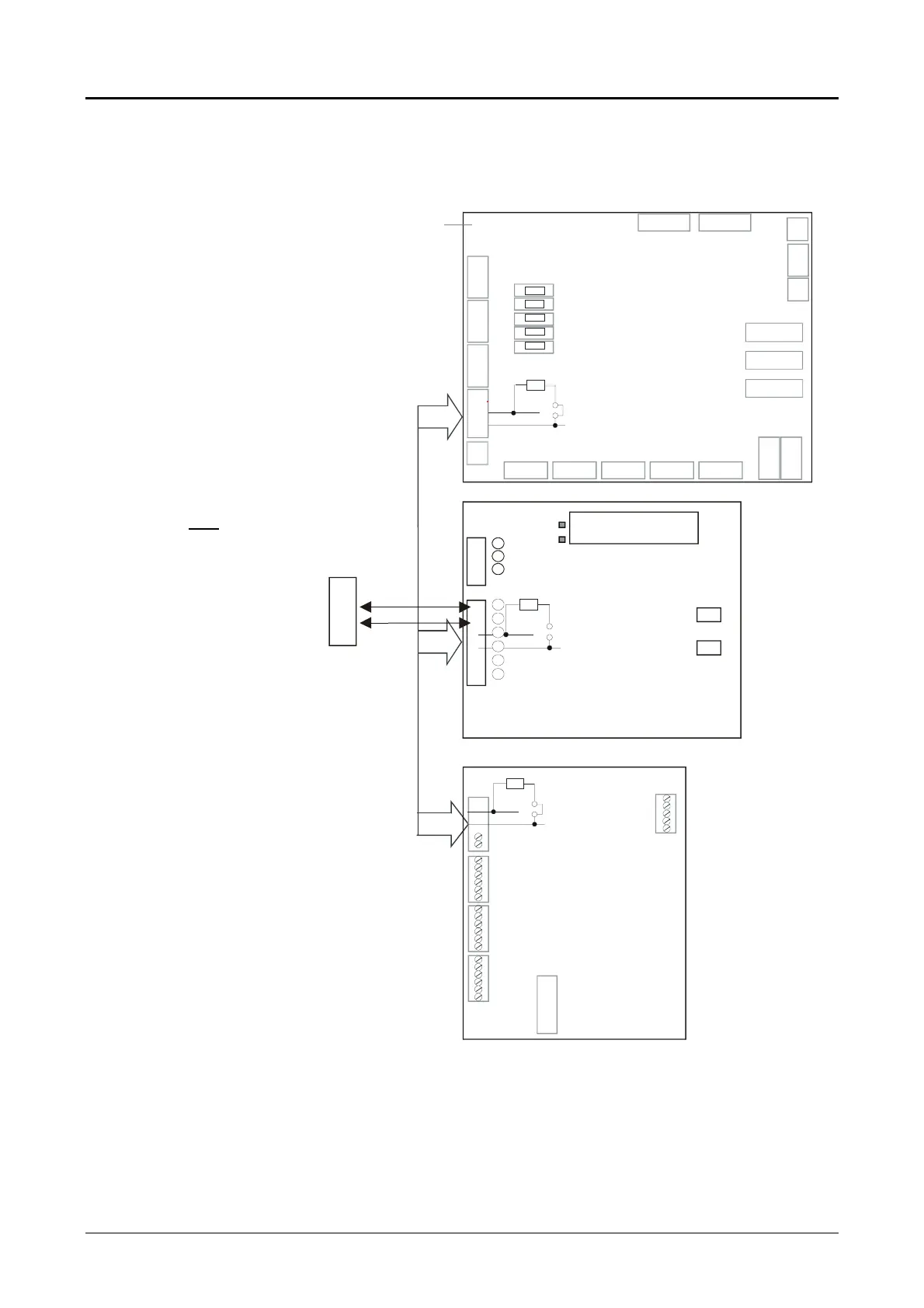
System databus connection diagram preferred wiring.
The “TERM” link is on the first and last devices
on the system databus. In a “star” wiring
configuration, the “TERM” link is only fitted
on the devices at the ends of the two longest
system databus cable runs.
➀ TERM link fitted (first device
on local databus)
➁ GND link fitted
➂ Control Panel ATS4000
➃ TERM link not fitted
➄ Remote arming station
➅ Separate 12 V power supply. Required if
RAS is more than 100 m from the nearest
panel or DGP. Connect “-“ to “-“ of the
databus
➆ TERM link fitted (last device on
local databus)
➇ Any data gathering panel like ATS1201
➈ Preferred data cable type is
Belden 8723 (2 pair twisted).
➉ System earth.
See: System databus connection and Earthing details on page 4
➈
➅
+
-
➃
SW1
SW2
+12 0V D+ D- IN OUT
Rx
Tx
ATS1105
➄
470
Ω
ATS1201
➇
➆
②
0
VD
+
D
-
+12345678-
470
Ω
②
ATS3000/4000.
③
+-
D
+
D
-
J14
J13
J16
J17
J6
J5
J4 J3
J2
J18
J8
J20
RX
TX
RX1
TX1
TH7
TH3
TH5
TH2
TH4
①
470
Ω
➉
EPROM
FLASH
RAM/IUM
J15
J7
RS
COMMS
J19
J10
J9
J2
J3
J3
J4
J6
J7
J8
 Loading...