ALTRAD8UD-1L
ALTRAD8UD-1L2T
24 25
English
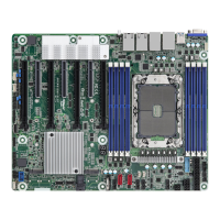
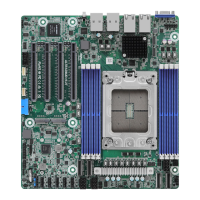
2.5 Expansion Slots (PCI Express Slots)
ere are 4 PCI Express slots on this motherboard.
PCIE slots:
PCIE4 (PCIE 4.0 x16 slot, from CPU1) is used for PCI Express x16 lane width cards.
PCIE5 (PCIE 4.0 x16 slot, from CPU1) is used for PCI Express x16 lane width cards.
PCIE6 (PCIE 4.0 x16 slot, from CPU1) is used for PCI Express x8 or x16 lane width cards.
PCIE7 (PCIE 4.0 x16 slot, from CPU1) is used for PCI Express x8 or x16 lane width cards.
Slot Generation Mechanical Electrical Source
PCIE4 4.0 x16 x16 CPU1
PCIE5 4.0 x16 x16 CPU1
PCIE6 4.0 x16 x8 or x16 CPU1
PCIE7 4.0 x16 x8 or x16 CPU1
* Supports PCIe4.0 x8 when using Ampere Altra processors
** SLOT4 do not support full-length card
Installing an expansion card
Step 1. Before installing an expansion card, please make sure that the power
supply is switched o or the power cord is unplugged. Please read the
documentation of the expansion card and make necessary hardware
settings for the card before starting the installation.
Step 2. Remove the system unit cover (if the motherboard is already installed
in a chassis).
Step 3. Remove the bracket facing the slot that intending to use. Keep the
screws for later use.
Step 4. Align the card connector with the slot and press rmly until the card is
completely seated on the slot.
Step 5. Fasten the card to the chassis with screws.
Step 6. Replace the system cover.
 Loading...