EasyManua.ls Logo

ASROCK G41M-S User Manual

ASROCK G41M-S
50 pages
To Next Page IconTo Next Page
To Previous Page IconTo Previous Page
Page #20 background imageLoading...
Page #20 background image
2020
2020
20
2.8 Onboard Headers and Connectors2.8 Onboard Headers and Connectors
2.8 Onboard Headers and Connectors
Onboard headers and connectors are NOT jumpers. Do NOT place
jumper caps over these headers and connectors. Placing jumper caps
over the headers and connectors will cause permanent damage of the
motherboard!
FDD connector
(33-pin FLOPPY1)
(see p.10 No. 20)
Note: Make sure the red-striped side of the cable is plugged into Pin1 side of the
connector.
Primary IDE connector (Blue)
(39-pin IDE1, see p.10 No. 7)
Note: Please refer to the instruction of your IDE device vendor for the details.
Serial ATAII Connectors These Serial ATAII (SATAII)
(SATAII_1: see p.10, No. 13) connectors support SATAII
(SATAII_2: see p.10, No. 12) or SATA hard disk for internal
(SATAII_3: see p.10, No. 10) storage devices. The current
(SATAII_4: see p.10, No. 11) SATAII interface allows up to
3.0 Gb/s data transfer rate.
Serial ATA (SATA) Either end of the SATA data cable
Data Cable can be connected to the SATA /
(Optional) SATAII hard disk or the SATAII
connector on the motherboard.
Serial ATA (SATA) Please connect the black end of
Power Cable SATA power cable to the power
(Optional) connector on each drive. Then
connect the white end of SATA
power cable to the power
connector of the power supply.
FLOPPY1
Pin1
the red-striped side to Pin1
connect the black end
to the IDE devices
connect the blue end
to the motherboard
80-conductor ATA 66/100 cable
IDE1
PIN1
connect to the SATA HDD
power connector
connect to the
power supply
SATAII_4
SATAII_3
SATAII_2
SATAII_1

Other manuals for ASROCK G41M-S

Question and Answer IconNeed help?

Do you have a question about the ASROCK G41M-S and is the answer not in the manual?

ASROCK G41M-S Specifications

General IconGeneral
Number of memory slots2
Maximum internal memory8 GB
Processor socketLGA 775 (Socket T)
Processor manufacturerIntel
Compatible processor seriesIntel® Celeron®
CPU fan connectorYes
Number of SATA connectors4
Number of Parallel ATA connectors1
Headphone outputs3
USB 2.0 ports quantityUSB 2.0 ports have a data transmission speed of 480 Mbps, and are backwards compatible with USB 1.1 ports. You can connect all kinds of peripheral devices to them.
Firewire (IEEE 1394) ports0
Audio chipRealtek ALC662
Power source typeATX
Audio output channels5.1 channels
Motherboard form factormicro ATX
Compatible operating systemsWindows 2000 / XP / XP 64-bit / Vista / Vista 64-bit
BIOS typeAMI
BIOS memory size64 Mbit
Maximum graphics card memory352 MB
Networking features10/100 Mb/s

Summary

Introduction

1.2 Specifications

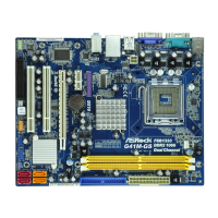
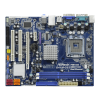
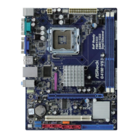
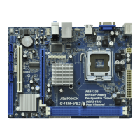
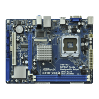
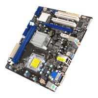
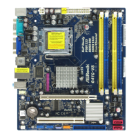
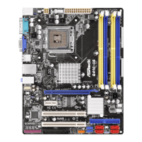
Details the technical specifications of the motherboard's platform, CPU, chipset, memory, expansion slots, graphics, audio, and I/O ports.

1.4 I/O Panel

Describes the rear panel connectors and their functions, including multi-streaming audio setup.

Motherboard Installation

2.2 Pre-installation Precautions

Essential safety and handling precautions before installing components to prevent static damage and physical injury.

2.3 CPU Installation

Step-by-step guide for correctly installing the Intel 775-LAND CPU into the motherboard socket.

2.4 Installation of CPU Fan and Heatsink

Instructions for mounting the CPU heatsink and fan, including thermal paste application and connector.

2.5 Installation of Memory Modules (DIMM)

Guide on installing DDR2 memory modules into the DIMM slots, emphasizing dual-channel configuration.

2.6 Expansion Slots (PCI and PCI Express Slots)

Explains the types of expansion slots (PCI, PCIe x1, PCIe x16) and how to install expansion cards properly.

2.8 Onboard Headers and Connectors

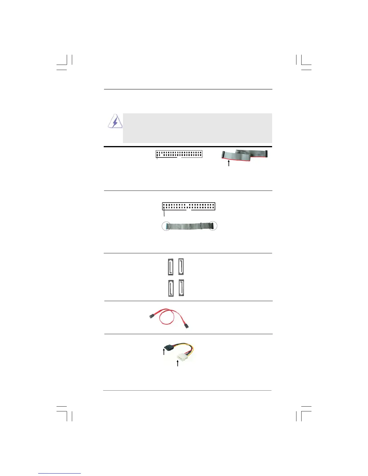
Identifies and describes onboard headers and connectors like FDD, IDE, SATA, USB, and front panel audio for system connection.

2.9 SATAII Hard Disk Setup Guide

Instructions for setting up SATAII hard disks to ensure optimal performance and compatibility with the motherboard.

BIOS Setup Utility

3.4.1 CPU Configuration

Settings for CPU frequency, overclocking mode, and other CPU-related features for performance tuning.

3.4.2 Chipset Configuration

Configuration options for DRAM frequency, timings, and memory remap features for memory performance.

3.5 Hardware Health Event Monitoring Screen

Monitoring of system hardware status like CPU temp, fan speed, and voltages for system health.

Related product manuals