EasyManuals Logo
Home>Asus>Motherboard>F1A55-M LX PLUS R2.0

Asus F1A55-M LX PLUS R2.0 User Manual

Asus F1A55-M LX PLUS R2.0
68 pages
To Next Page IconTo Next Page
To Previous Page IconTo Previous Page
Page #33 background imageLoading...
Page #33 background image
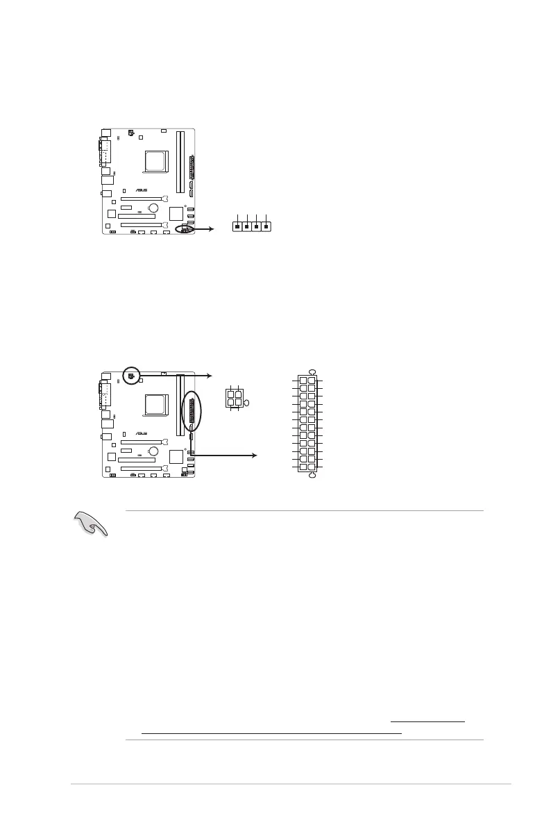
2. Speaker connector (4-pin SPEAKER)
This 4-pin connector is for the chassis-mounted system warning speaker. The speaker
allows you to hear system beeps and warnings.
3. ATX power connectors (24-pin EATXPWR, 4-pin ATX12V)
These connectors are for an ATX power supply. The plugs from the power supply are
designed to t these connectors in only one orientation. Find the proper orientation and
push down rmly until the connectors completely t.
We recommend that you use an ATX 12V Specication 2.0-compliant power supply unit
(PSU) with a minimum of 300W power rating. This PSU type has 24-pin and 4-pin power
plugs.
If you intend to use a PSU with 20-pin and 4-pin power plugs, ensure that the 20-pin
power plug can provide at least 15 A on +12 V and that the PSU has a minimum power
rating of 300W. The system may become unstable or may not boot up if the power is
inadequate.
DO NOT forget to connect the 4-pin ATX +12V power plug. Otherwise, the system will
not boot up.
We recommend that you use a PSU with higher power output when conguring a
system with more power-consuming devices or when you intend to install additional
devices. The system may become unstable or may not boot up if the power is
inadequate.
If you are uncertain about the minimum power supply requirement for your system,
refer to the Recommended Power Supply Wattage Calculator at http://support.asus.
com/PowerSupplyCalculator/PSCalculator.aspx?SLanguage=en-us for details.
F1A55-M LX PLUS R2.0
F1A55-M LX PLUS R2.0 Speaker out connector
+5V
GND
GND
Speaker Out
SPEAKER
PIN 1
F1A55-M LX PLUS R2.0
F1A55-M LX PLUS R2.0 ATX power connectors
EATXPWR
PIN 1
GND
+5 Volts
+5 Volts
+5 Volts
-5 Volts
GND
GND
GND
PSON#
GND
-12 Volts
+3 Volts
+3 Volts
+12 Volts
+12 Volts
+5V Standby
Power OK
GND
+5 Volts
GND
+5 Volts
GND
+3 Volts
+3 Volts
ATX12V
PIN 1
+12V DC
+12V DC
GND
GND
ASUS F1A55-M LX R2.0 Series 1-23

Table of Contents

Other manuals for Asus F1A55-M LX PLUS R2.0

Questions and Answers:

Question and Answer IconNeed help?

Do you have a question about the Asus F1A55-M LX PLUS R2.0 and is the answer not in the manual?

Asus F1A55-M LX PLUS R2.0 Specifications

General IconGeneral
Non-ECCYes
Memory channelsDual-channel
Memory slots typeDIMM
Number of memory slots2
Supported memory typesDDR3-SDRAM
Maximum internal memory32 GB
Supported memory clock speeds1066, 1333, 1600, 1866, 2250 MHz
Processor socketSocket FM1
Processor manufacturerAMD
Compatible processor seriesAMD A, AMD E2
Maximum number of SMP processors1
USB 2.0 connectors3
Power fan connectorNo
Number of SATA II connectors6
USB 3.2 Gen 1 (3.1 Gen 1) connectors0
Controller interface typeAMD A55 FCH
USB 2.0 ports quantityUSB 2.0 ports have a data transmission speed of 480 Mbps, and are backwards compatible with USB 1.1 ports. You can connect all kinds of peripheral devices to them.
Audio chipRealtek ALC887
Cooling typePassive
CertificationRoHS\\r ErP Ready
Component forPC
Power source typeATX
Motherboard chipsetAMD A55
Audio output channels7.1 channels
Motherboard form factormicro ATX
RAID levels0, 1, 10, JBOD
Supported storage drive interfacesSATA II
Graphics cardRadeon HD 6000
DirectX version11
Maximum resolution1920 x 1200 pixels
Parallel processing technology support2-Way CrossFireX, LucidLogix Virtu
PCI Express slots version2.0
PCI Express configurations1x1, 1x4, 1x16
Trial softwareAntivirus
Cables includedSATA
Bundled softwareASUS utilities\\r ASUS Update
LAN controllerRealtek RTL8111E
Ethernet interface typeGigabit Ethernet
BIOS typeUEFI
ACPI version3.0
BIOS memory size64 Mbit
Weight and Dimensions IconWeight and Dimensions
Depth213 mm
Width244 mm

Related product manuals