ASUS P5B-MX/WiFi-AP 1-9
1.5.4 Layout-Inhalt
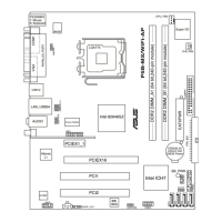
Steckplätze Seite
1. DDR2 DIMM-Steckplätze 1-17
2. PCI-Steckplätze 1-25
3. PCI Express x1-Steckplätze 1-25
4. PCI Express x16-Steckplatz 1-25
Jumper Seite
1. RTC RAM (3-pol. CLRTC) 1-26
2. USB-Gerät-Weckfunktion (3-pol. USBPW1-4, USBPW56, USBPW78) 1-27
3. Keyboard Power (3-pin KBPWR) 1-27
Rückseitenanschlüsse Seite
1. PS/2-Mausanschluss (grün)
1-28
2. Parallele Schnittstelle
1-28
3. LAN (RJ-45)-Anschluss 1-28
4. Line In-Anschluss (hellblau) 1-28
5. Line Out-Anschluss (hellgrün) 1-28
6. Mikrofonanschluss (rosa) 1-28
7. WiFi-g-Antennenanschluss 1-29
8. ASUS Wi-Fi AP Solo™ LED-Anzeige 1-29
9. USB 2.0-Anschlüsse 1 und 2 1-29
10. USB 2.0-Anschlüsse 3 und 4 1-29
11. VGA-Anschluss 1-29
12. Serielle Schnittstelle 1-29
13. PS/2-Tastaturanschluss (lila) 1-29
Interne Anschlüsse Seite
1. Diskettenlaufwerksanschluss (34-1 pol. FLOPPY) 1-30
2. Digitaler Audioanschluss (4-1 pol. SPDIF_OUT) 1-30
3. IDE-Anschluss (40-1 pol. PRI_IDE) 1-31
4. ICH7 Serial ATA-Anschlüsse (7-pol. SATA1, SATA2,SATA3, SATA4) 1-32
5. USB-Anschlüsse (10-1 pol. USB56) 1-33
6. Audioanschluss für das optische Laufwerk (4-pol. CD) 1-33
7. CPU- und Gehäuselüfteranschlüsse (4-pol. CPU_FAN, 1-34
3-pol. CHA_FAN)
8. Gehäuseeinbruchsanschluss (4-1 pol. CHASSIS) 1-35
9. Fronttafelaudioanschluss (10-1 pol. AAFP) 1-35
10. ATX-Netzanschluss (24-pol. EATXPWR, 4-pol. ATX 12V) 1-36
11. Systemtafelanschluss (20-8 pol. PANEL) 1-37
 Loading...