Reference Description
6 Manual condensate drain
7 Hole, 15 x 25 (3X)
8 Receiver
9 Cooling air inlet
10 Motor cooling air inlet
11 Compressed air outlet
13 Compressor cooling air and air inlet
14 For dismantling air filter
15 Compressor air outlet with flexible (2 meters)
16 Electric cable entry (on rear side)
19 Air outlet
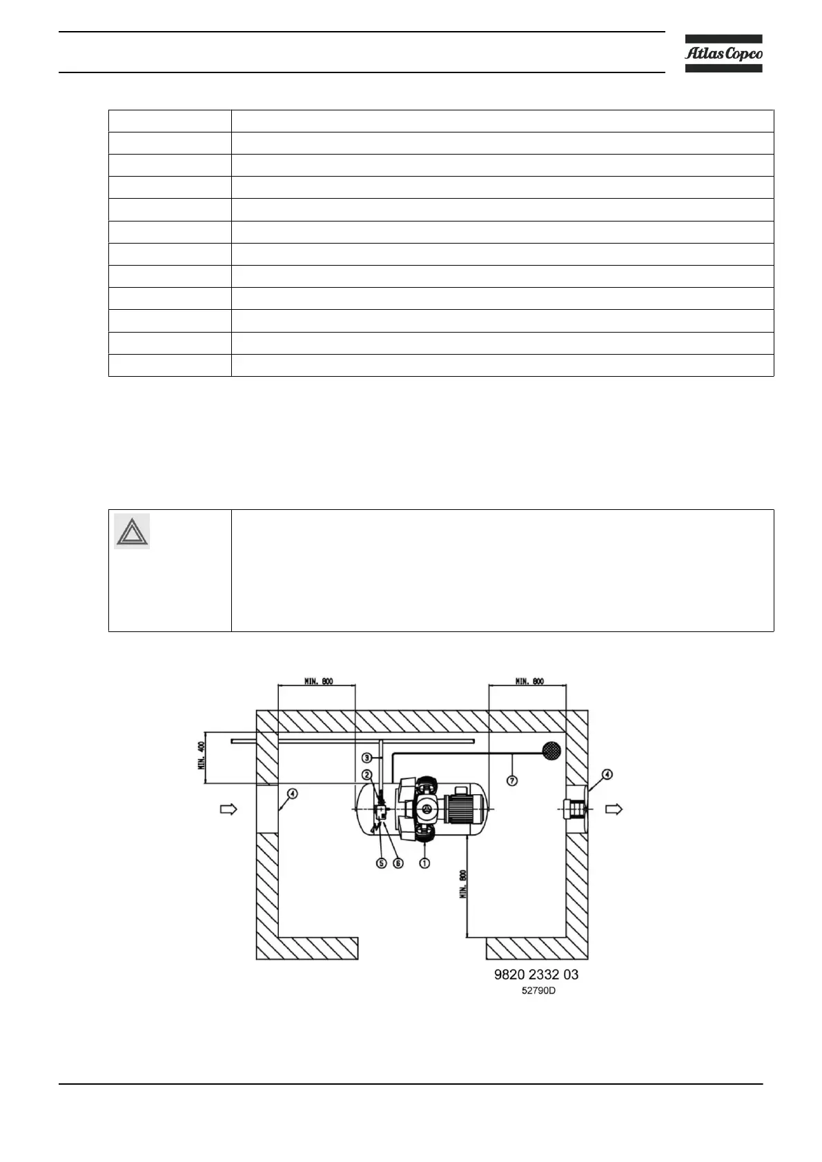
3.2 Installation instruction
Install the unit in an area where the noise levels do not cause inconvenience and adequate ventilation is
available for cooling purposes.
Before commencing installation, check that the electrical data on the compressor
specification plate/s are compatible with the local power supply. Before connecting, the
electricity, ensure that the power supply is off and correctly isolated.
The electrical power supplied to the compressor unit must be connected by a qualified
electrician in accordance with the wiring diagram supplied with the plant. All wiring must
be in accordance with IEE regulations. Cable sizes given in section. Electric data are
recommendations only.
Installation proposal for tank-mounted unit (90 l receiver)
Instruction book
2920 7089 90 39