18
XAVS 136 Dd - XAHS 146 Dd - XATS 156 Dd - XA(S) 186 Dd - XAHS 186 Dd
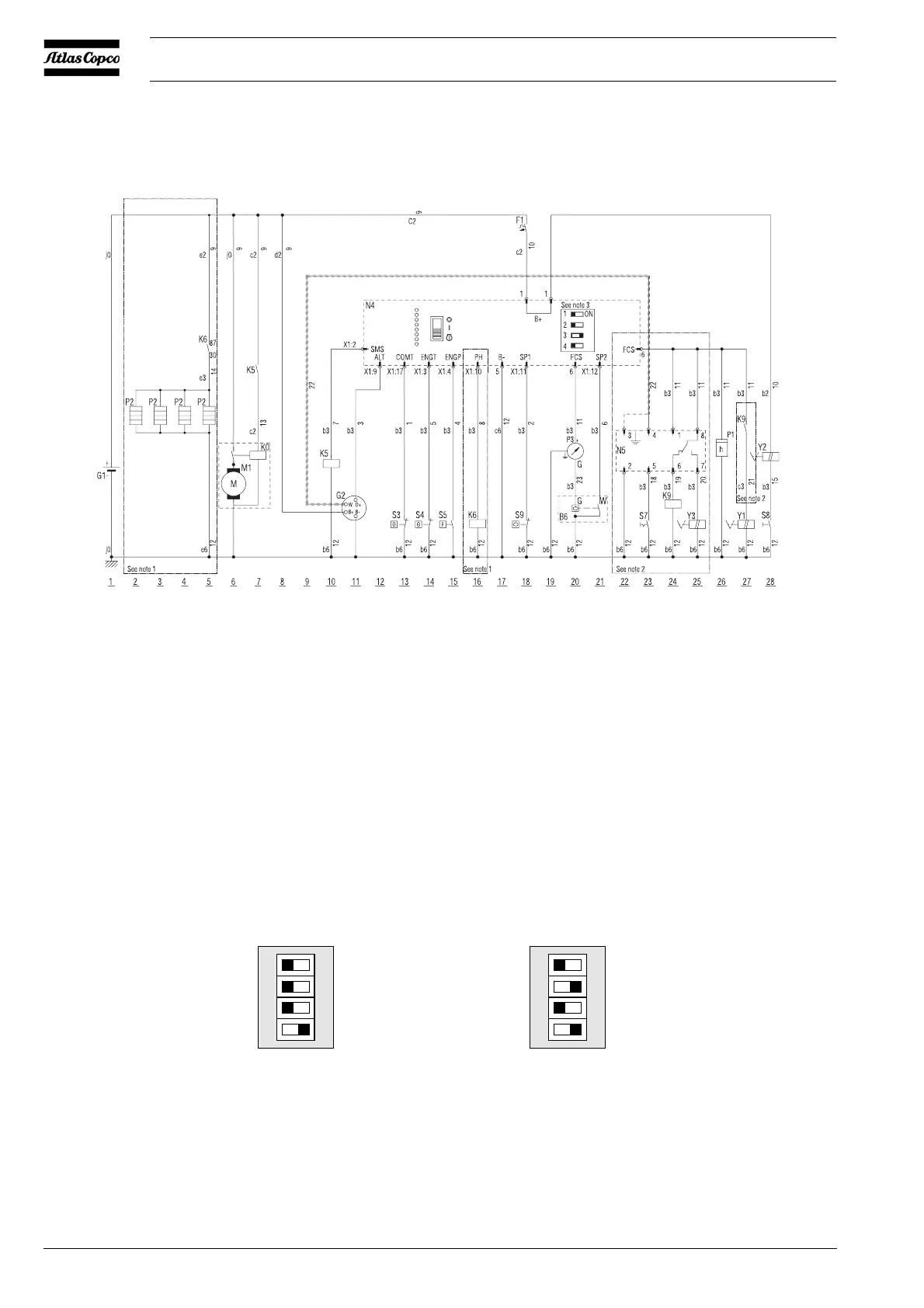
2.8.2 CIRCUIT DIAGRAM FOR XAHS 186 DD
The compressor is equipped with a negative earthed system.
Fig. 2.8 Dip switches
Fig. 2.7 Circuit diagram (Nr. 9822 0893 12)
Note:
1 To be used with Cold Start Option.
2 To be used with Refinery Equipment.
3 Position of DIP-switches.
B6 Fuel Level Sensor
F1 Circuit Breaker
G1 Battery 12V
G2 Charging Alternator
K0 Starter Solenoid
K5 Auxiliary Starter Relay
K6 Cold Start Relay
K9 Overspeed Relay
M1 Starter Motor
N4 Control Module
N5 Overspeed Control Module
P1 Hourmeter
P2 Glowplug
P3 Fuel Level Gauge
S3 Compressor Temperature Switch
S4 Engine Temperature Switch
S5 Engine Low Oil Pressure Switch
S7 Overspeed Control Test Switch
S8 Push Button
S9 Coolant Level Switch
X1 Module Connector
Y1 Fuel Stop Solenoid
Y2 Excess Fuel Provider
Y3 Overspeed Solenoid
ote:
For correct functioning of the module, the dip switches at the back of the module should be positioned as follows
Standard (no coldstart) With coldstart option
Not used
Preheat-Coldstart
Low fuel level
Low coolant level
 Loading...