32
XAVS 136 Dd - XAHS 146 Dd - XATS 156 Dd - XA(S) 186 Dd - XAHS 186 Dd
5. ADJUSTMENTS AND SERVICING PROCEDURES
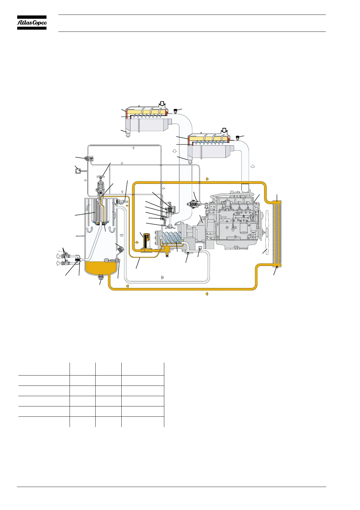
5.1 ADJUSTMENT OF THE CONTINUOUS REGULATING SYSTEM
The working pressure is determined by the tension of the spring in the
regulating valve (RV). This tension can be increased to raise the
pressure and decreased to lower it by turning the adjusting wheel
clockwise and anti-clockwise respectively.
To adjust the normal working pressure, proceed as follows:
1. Start and warm up the engine (see section 3.3).
2. With the outlet valves (AOV) closed, loosen the regulating valve’s
lock nut and adjust the regulating valve (RV) until a pressure of
X bar(e) is reached (see table).
3. Check the minimum speed of the engine. Adjust minimum speed
stop screw if necessary.
4. Open an outlet valve (AOV) just enough to let the engine (E) run
at maximum speed. The working pressure must be Y bar(e); adjust
if necessary with regulating valve (RV) (see table).
5. Check the engine maximum speed. Adjust the maximum speed
by means of adjusting eccentric nut on top of speed regulator (SR).
6. Close the outlet valves (AOV), check that the pressure is between
Z1 and Z2 bar(e) (see table). Lock the regulating valve (RV) by
fixing the lock nut.
(BOV)
(AF
CE)
(L
V)
(DP)
(MPV)
(NR
V)
(UV)
(UA)
(VH)
(BDV)
(CV)
(CH)
(AOV)
(AF
E)
(R
V)
(SR)
(VV)
(VI)
(VV)
(SV)
(FR)
(PG)
(AR)
(DP)
(OLG)
(SL)
(FP)
(SL)
(OF)
(CE)
(DP)
(TS)
(F)
(OC
CE)(E)
(VI)
(SC)
(SC)
(OS)
Fig. 5.1 Regulating system
X
bar(e)
Y
bar(e)
Z1 – Z2
bar(e) bar(e)
XAVS 136 Dd 15.5 14 15.3 – 15.7
XAHS 146 Dd 13.5 12 13.2 – 13.6
XATS 156 Dd 11.8 10.3 11.7 – 12.2
XA(S) 186 Dd 8.3 7 8.1 – 8.5
XAHS 186 Dd 13.5 12 13.3 – 13.7
 Loading...