- 19 -
5.4 Connecting FXS Analog Interfaces
The device interfaces with FXS analog telephone equipment (e.g., fax machines, modems, or
telephones) through the 50-Pin D-Sub connectors on the rear panel:
◼ 50-Pin D-Sub female connector for FXS ports 1-24.
◼ 50-Pin D-Sub female connector for FXS ports 25-32.
The 50-Pin D-Sub connector for FXS ports 25-32 is available only for MP-532.
FXS Outdoor Cabling and Power Surge Protection
◼ The device includes an integrated secondary surge protection, but not a primary
telecom protection! When the FXS telephone lines are routed outside the building,
additional protection, usually a 350V three-electrode Gas Discharge Tube (GDT) as
described in ITU-T K.44, must be provided at the entry point of the telecom wires into
the building (usually on the main distribution frame or MDF) in conjunction with
proper grounding. The center pin of the GDT (MDF grounding bar) must be connected
to the equipotential grounding bus bar of the Telecommunication room.
◼ Failure to install primary surge protectors and failure to comply with the grounding
instructions or any other installation instructions may cause permanent damage to the
device.
◼ The device complies with protection levels as required by EN 55035/ EN 300386.
Higher levels of surges may cause damage to the device.
◼ To protect against electrical shock and fire, use a minimum of 26-AWG wire size to
connect the FXS ports
◼ Make sure that you connect the FXS ports to appropriate external devices; otherwise,
damage to the device may occur.
◼ FXS ports are considered TNV-2.
FXS cabling specifications:
◼ Cable: You can use any of the following cables:
• AudioCodes orderable FXS Patch Panel (see Connecting FXS Interfaces using AudioCodes
FXS Patch Panel on the next page)
• AudioCodes orderable 50-Pin D-Sub connector cable (10 m) to open leads, which needs
to be connected to a distribution panel (see Connecting FXS Interfaces using Centronics
Cable on page 28)
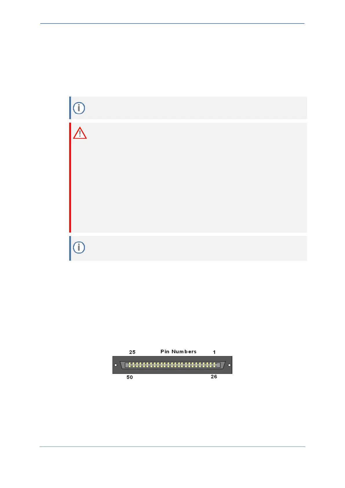
◼ Connector Type: 50-Pin D-Sub
Figure 13: 50-Pin D-Sub Connector

 Loading...